WindMaster and WindMaster Pro 1561-PS-0001. Issue 11 February 2017
________________________________________________________________________________________________________________________
26
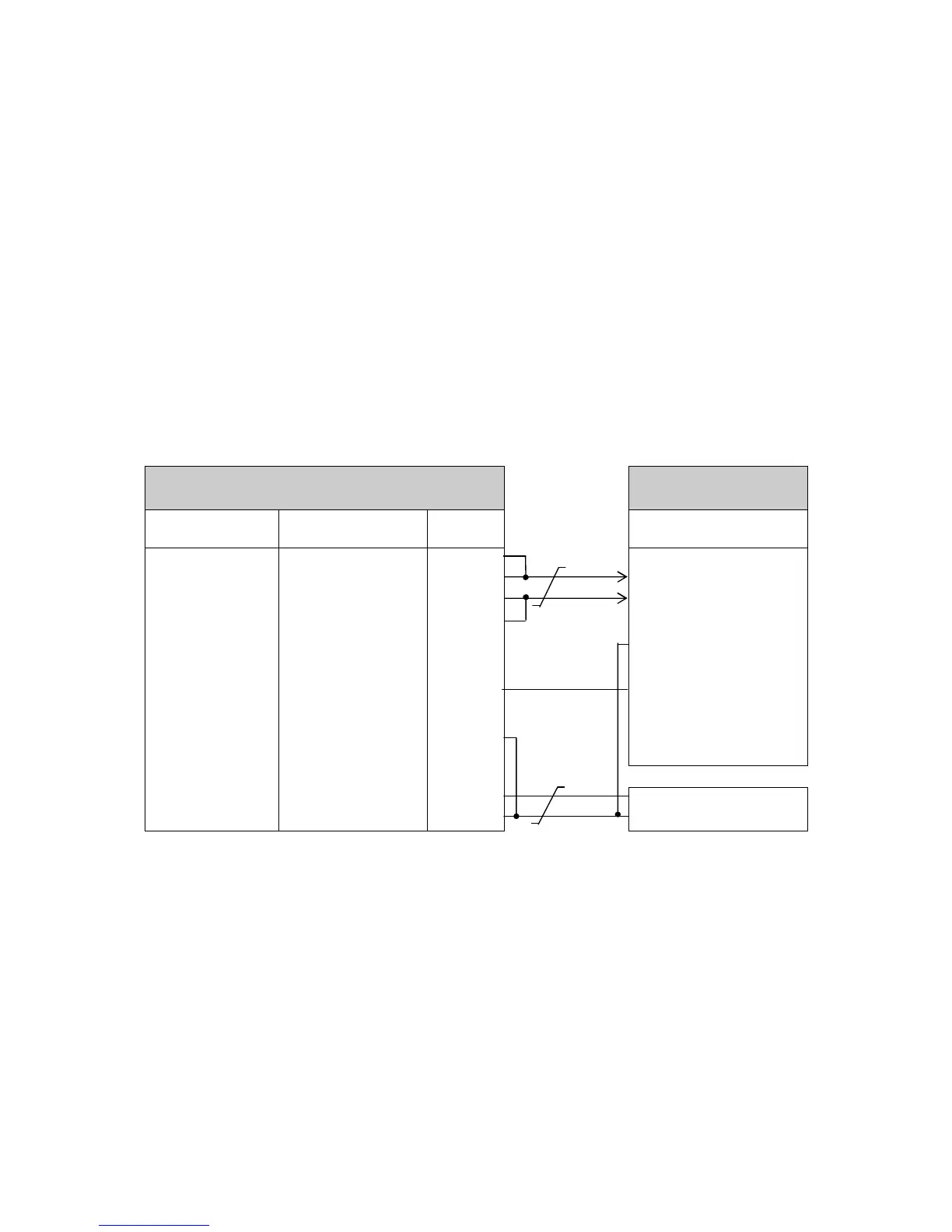
6.10. Using RS485, 2 Wire, WindMaster/WindMaster Pro Networking
Notes:-
1. These notes apply to using WindMasters and WindMaster Pro’s only on a 2 wire RS485 network.
2. Set up the WindMaster operating configuration before wiring for RS485 mode.
3. WindMasters must be configured for RS485 by linking Comms Mode line (Pin 4) to 0V (Pin 12).
4. On Pipe Mount box units set J4 Link to COM/CM and externally link Comms mode to Power V+ or internally
move link from J4 COM/CM to between COM and V+.
5. On non pipe mount box units if Pin 4 is left open circuit the unit will default to RS422 operation in Auto mode.
6. WindMasters must be in a Polled mode.
7. The baud rate setting may need to be adjusted/increased to 38400 or above depending on the poll rate.
8. The Master unit can be any suitable control device fitted with a RS485 interface card, such as a PC or Data
logger. For best operation then the units should be connected directly to an RS485 interface card, use of some
converters may degrade operation.
9. Analogue Outputs are also simultaneously available.
10. Node IDs of A-F, K, M, N or P are not recommended to use in a multi-drop system as these letters may appear
in the WindMaster data string.
11. See Para 7.3 for more details on Poll operation.
 Loading...