18
860-7200-18 DTU DTB Service & Maintenance Manual
time, date, machine being serviced, and reason for the lock
out�
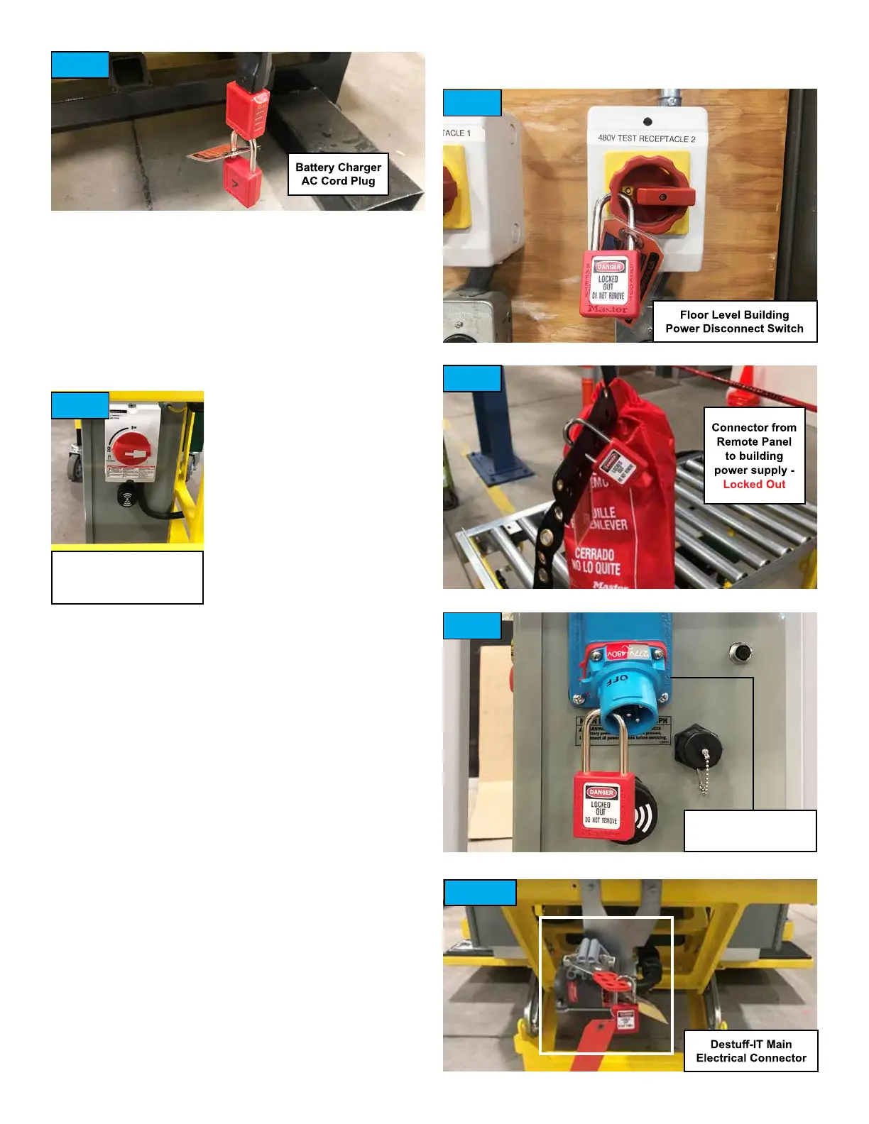
4� Lockout and tag the AC cord plug for the battery charger
(located at rear of Destu-it, under the rear conveyor). The
tag should indicate the employee name, time, date, machine
being serviced, and reason for the lockout� (Fig� 5)
5� Turn OFF the switch for the buildings power supply line which
controls power to the Destu-it power drop. Lockout and tag
the switch which controls this power supply line� The tag
should indicate the employee
name, time, date, machine being
serviced, and reason for the lock
out�
6� Verify that there is no
voltage present at the power
drop connector for the Destu-it
remote section�
7� After verifying there is no
voltage present, unplug the
connectors at the power drop
to the remote section� NEVER
unplug the connectors unless
the power supply has rst been turned OFF.
8� Lockout and tag the remote panel connector (not the
building side of connector)� The tag should indicate the
employee name, time, date, machine being serviced, and
reason for the lock out� If the remote panel is equipped with a
Meltric connector, unplug it and lock it out as shown� (Fig� 9)
9� Disconnect the main electrical connector on the rear of the
Destu-it. It may be necessary to mechanically separate the
Destu-it machine from the Flex or Gawronski conveyors to
access the connector. Lockout and tag the main Destu-it
electrical connector (Fig� 10)� The tag should indicate the
employee name, time, date, machine being serviced, and
reason for the lock out�
Verify that the safety block is properly installed on the hydraulic
rod for front conveyor� (Fig� 2)
Verify both AC disconnect switches are turned OFF� (Fig� 4 and 6)
Verify that there are lockouts and tags installed on:
• DC disconnect switch on Drive Panel� (Fig� 4)
• AC plug for battery charger at bottom, rear of Destu-it. (Fig. 5)
• Building power supply switch to Destu-it Power Drop. (Fig. 7)
• Remote Panel side of power drop connector� (Fig� 8 or Fig� 9)
• Main electrical connector for Destu-it at back of machine.
(Fig� 10)
• Where the possibility of induced voltages or stored electrical
energy exists, such as in the case of Control Panels with a VFD,
wait 15 minutes to ensure the lights and indicators are out on
the VFD and to allow the DC bus capacitors to discharge�
AC Disconnect Switch
(if equipped - optional)
Fig. 5
Fig. 6
Fig. 7
Fig. 8
Fig. 9
Fig. 10
Meltric Connector
(if equipped)