17
860-7200-18 DTU DTB Service & Maintenance Manual
against the safety block and prevents it from lowering any
further� Continue to hold the rotary handle until the operator
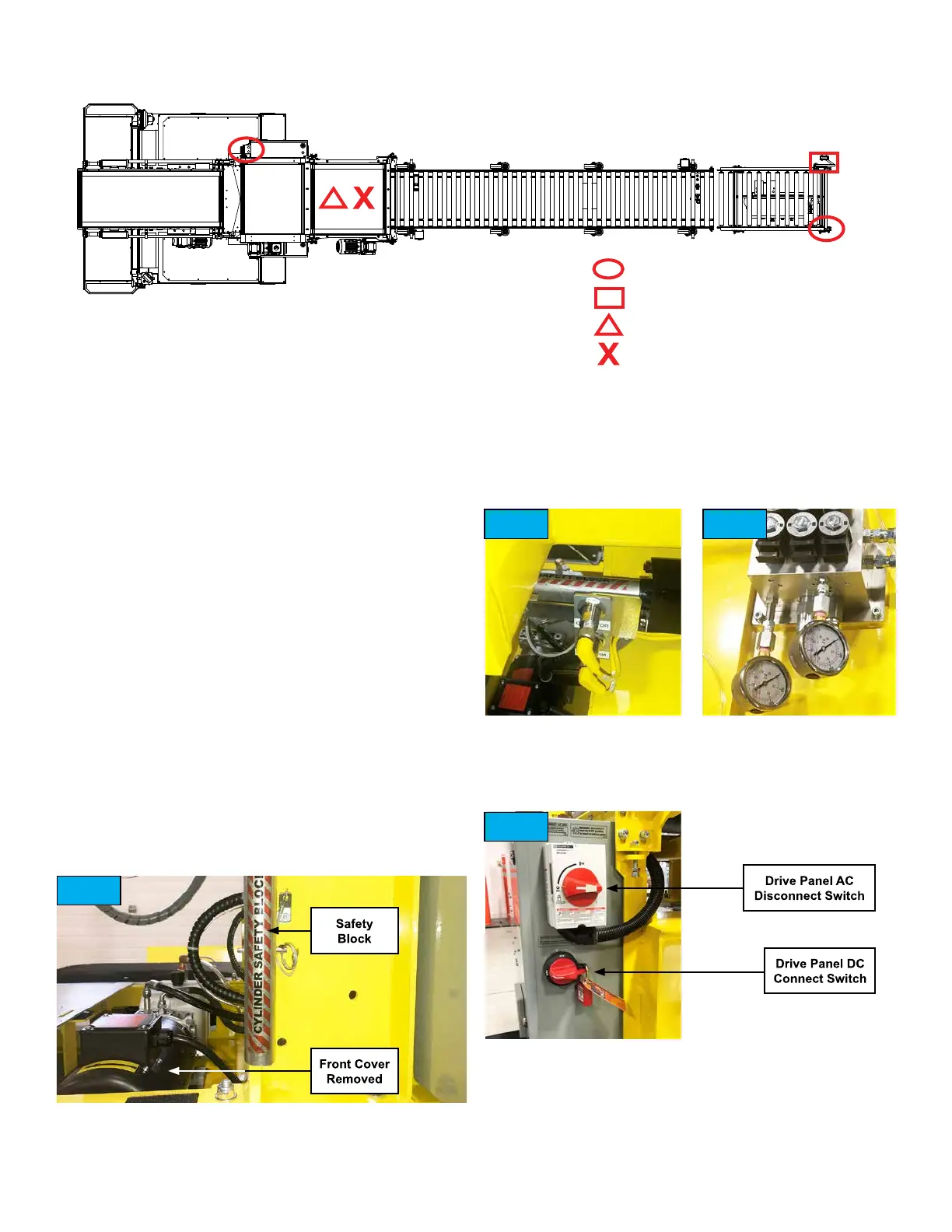
platform has reached its lowest position� Remove the cover
over the hydraulic pump� Conrm that both hydraulic
pressure gauges read “0” psi. (Fig. 3)
2� Turn OFF both of the AC disconnect switches� (Fig� 4 & 6)
One is on the Remote Panel (if equipped with this option)
and the other is on the Drive Panel� Turn OFF the DC
disconnect switch on the Drive Panel� (Fig� 4)
3� Lockout and tag the DC disconnect switch on the Drive
Panel� (Fig 4) The tag should indicate the employee name,
SAFETY LOCKOUT/TAGOUT PROCEDURE
ONLY TRAINED AUTHORIZED PERSONNEL SHALL
CONDUCT LOCKOUT PROCEDURES
IMPORTANT: Only persons who are appropriately trained
and qualied with the safe operation and service of this machine
should be allowed to carry out operation, installation, service or
maintenance� Trained personnel must follow all applicable codes,
laws and standards, both national and local, when conducting any
servicing or maintaining of the machine and associated equip-
ment� Trained personnel should know and follow all national and
local regulations regarding occupational health and safety acts
or regulations� These persons must also have received safety
training to recognize, identify and avoid any hazards involved in
servicing and maintaining the equipment� Service personnel shall
also notify and inform any employee or individual aected by the
shutdown and lockout, tagout of the equipment, even if they are
not involved in the service or maintenance work� Service person-
nel must use any protective equipment, protective devices and
clothing required in accordance with all governing acts, laws and
the employer�
1� The AC power must be connected and turned ON to the
Destu-it machine before locking out the machine. Turn
ON the Destu-it machine. While standing on the operator
platform, use either rotary handle control to raise the front
conveyor to its full height� Remove the safety block from its
stored position on the left side of the machine� (Fig� 1) Place
the safety block over the top of the front conveyor’s hydraulic
cylinder rod and insert the pin to prevent it from falling o.
(Fig� 2) Stand on the operator platform and use the rotary
handle to lower the front conveyor so the front conveyor rests
Power Drop Connector
AC and DC Disconnect Switches
AC Battery Charger Plug
Destu-it Main Electrical Connector
Fig. 1
Fig. 2
Fig. 4
Fig. 3