57
860-7200-18 DTU DTB Service & Maintenance Manual
REPLACING THE HYDRAULIC FLUID
IMPORTANT: Only persons who are appropriately trained and
qualied with the safe operation and service of this machine
should be allowed to carry out operation, installation, service or
maintenance� Trained personnel must follow all applicable codes,
laws and standards, both national and local, when conducting
any servicing or maintaining of the machine and associated
equipment� Trained personnel should know and follow all national
and local regulations regarding occupational health and safety
acts or regulations� These persons must also have received safety
training to recognize, identify and avoid any hazards involved in
servicing and maintaining the equipment�
The hydraulic uid and pump lter in the Destu-it machine
should be changed every 2,000 hours of operation� Hydraulic
pump service kit part # 23463100 and Tank Seal O-ring #
273111110004 Is required.
1� Operate the hydraulic system under normal operating
temperature and conditions for a minimum of one hour� The
lubricant (ISO VG-46 AW) in the system should be warm prior
to replacement�
2. Complete Destu-it Safety Lockout Procedures –
Document 860-6000
3� Remove the cover over the hydraulic pump and tank� It is
held in place with Velcro� Remove the four screws from the
pump’s electrical junction box cover plate� Note the colour
coding of the wire connections inside the box, to allow it to
be reconnected the same way� Disconnect the wires and the
ground inside the box�
4� Disconnect the clear uid return lines from the tank by gently
pulling back the plastic release connector at the top of the
tank� Disconnect the two hydraulic lines at the pump, which
connect the pump and manifold� Use clean rags to absorb
any residual oil from the lines and prevent dirt/debris from
entering them�
5� Remove the four bolts securing the pump bracket to the
base� Remove the two fasteners that secure the tank support
bracket to the base (if equipped with support bracket)�
(Extreme caution should be exercised when draining hot
lubricant to prevent possible injury or spills).
6� Remove the pump and tank from the machine on to a work
bench. Drain the uid from the tank by using a small uid
transfer pump� Use a suitable container to recover the old
uid in order to dispose of it properly.
7� Remove the four bolts/clamps which hold the tank to the
pump� Gently separate the tank from the pump, being careful
not to damage or deform the tank�
8� Thoroughly clean the inside of the tank to remove any sludge
or residual uid. Make sure the tank is clean and dry on the
inside�
9� Remove the hose clamp securing the suction lter to the
pump. Replace the suction lter, hose clamp and small O-ring
on the connecting tube� Use service kit Part # 23463100
(includes lter, hose clamp and O-ring). Use a small amount
of new uid to lubricate the O-ring before installing it and the
new lter. Clean any dirt/debris from the exposed portion of
the pump which is normally inside the tank�
10� Replace the large O-ring - part # 273111110004 (110 x 4 mm)
to prevent leaks between the tank and pump from occurring�
Coat the large O-ring on the pump with new uid to prevent
the tank from damaging it when re-installing it. Fasten
the tank to the pump using the four bolts/clamps� Do not
overtighten the bolts which could deform the plastic tank and
cause a leak to occur�
11� Re-install the pump and tank into the Destu-it machine.
Fasten the pump and tank to the base using the bolts
removed earlier�
12� Reconnect the two hydraulic hoses to the pump� Push the
connector with the two clear uid return lines on to the tting
on the top of the tank�
13� Reconnect the pump wiring and insure the ground wire is
connected. Re-install the cover plate and screws.
14� Fill the hydraulic tank with 4.5 litres of fresh oil - ISO VG-46
AW hydraulic uid.
15. Remove all the Destu-it lockouts. See document DT-SB
19-004.
16� Follow the machine start-up instructions. Use the rotary
handle on the front conveyor to raise the operator platform
and front conveyor� Run the operator platform and front
conveyor all the way up and down for a few minutes to
remove any air from the system�
Check for any uid leaks before returning the machine to service.
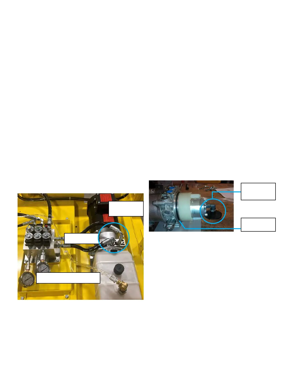
Pump suction
lter and hose
clamp
Large O-Ring
seals tank
Pump Electrical
Junction Box
Hydraulic Lines
Fluid Return Lines Connector