56
860-7200-18 DTU DTB Service & Maintenance Manual
10. Installing the New Brake
Install the shoulder bolt and hex bolt through the new brake
to fasten it to the brake mounting plate but don’t tighten them�
Leave them slightly loose to allow the new brake to slide into
place� Loosen the four inline bolts that secure the bottom
brake pad and spacer to the main brake assembly� Loosen
them enough so the brake disc will slide into place between
the pads during step 11� Place a support underneath the
brake and mounting plate near the brake disk� A cardboard
box will work� Connect the hydraulic hose to the brake�
Ensure the ttings are seated correctly and are tight. If the
brake bleeder tting is in that position, relocate it to the same
side as it is on the original brake. Ensure there is uid in the
hydraulic tank. The level of uid should be about 1-1/2 inches
below the top of the tank when full. Don’t overll the tank.
Use AWG 46 if some must be added�
11. Remove the all the Lockouts – See Document 860-6000.
Once the machine is connected to AC power and started, use
the brake release switch on the left mast to open the brake
caliper� The brake will remain open so long as the machine
remains ON (6-minute no activity timer) and the brake
release switch is towards the “I” position� If the brake caliper
doesn’t open far enough – do step 13 (bleed brake). Slide
the brake and plate into place over the caliper disk. Re-install
the brake plate mounting hardware and shims (usually two
shims/side)� Tighten the shoulder bolt and hex bolt and nuts
under the plate� There must be at least a 1/8” gap between
the bolt heads and the brake and the brake to the brake
mounting plate. This provides clearance for the brake body
to slide up and down� Tighten four inline bolts on the bottom
of the brake to 30 lb-ft.
12� With the machine started, one person turns o the brake
release switch and another person cycles the brake while
the rst person watches it open and close. Use the brake
release switch� Verify a small gap (1/16”) appears between
the underside of the caliper disc plate and the top of the lower
brake pad� Verify the upper brake pad passes evenly over
the top of the brake disc as the front conveyor is pivoted side
to side� If it does not pass evenly and there is a gap between
the upper pad and caliper disc on one side, adjust the brake
mounting bracket with shims until it’s even� Ensure all
adjustments are correct and hardware is tight.
13� Use the bleeder valve on the right side of the brake to bleed
air out of the hydraulic system� Attach a clear hose and bucket
to capture expelled uid. Add new clean uid to the pump
reservoir if the level is low� Activate the brake release and
open the bleeder to allow air to escape the brake� Tighten the
bleeder and engage the brake� Repeat the process until no air
bubbles are seen in the hose coming out of the brake when it’s
cycled ON/OFF�
14� Once all checks on the brake are complete, turn the AC
disconnect switch on the Remote Panel to OFF and Lock it
out or turn the AC selector switch on the top of the left mast
to the “O” position and unplug the Meltric connector on the
remote panel (depends on what options the machine is built
with)� Unplug the main electrical connector at the side of the
3rd conveyor� Move the rear support frame back into position
and re-install the clevis pins and cotter pins. Move the upper
rear conveyor into place� Twist and lower the assembly to get
the two rollers into the slots in the frame assembly they slide
in� Position the front edge of the conveyor section against
the machine. Re-install the pivot pins and secure them with
the four bolts. Attach the Destu-it main electrical connector
back onto it’s mounting bracket� Secure the 3rd conveyors
motor cable (if equipped) to the main electrical harness with
tie straps� Plug in the main electrical connector and fasten the
strain relief cable. Re-install the white plastic transition plate
between the rear and middle conveyor belts� Ensure it is
evenly spaced between the two belts to prevent belt wear.
Re-install the ground strap. Remove AC disconnect lockout if
present or reconnect Meltric connector on Remote panel�
15� Start the Destu-it machine and test it prior to returning it to
service�
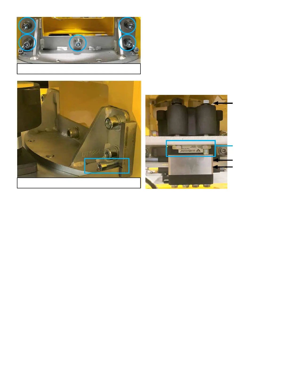
Mounting bolts (5) to level caliper disc
Jacking screws (2) to square up mount to frame
Leave approx. 1/8” gap
under both bolt heads
and between brake and
mounting plate.
No gap between pad
and disc.
1/8” gap when brake is
released. No gaps when
brake is applied.
Tighten nuts after bolts
are set.