55
860-7200-18 DTU DTB Service & Maintenance Manual
5� Place rags or absorbent material over the battery cover plate
to catch any hydraulic uid spills. Disconnect the hydraulic
hose at the left side of the brake� Cover the end of the hose
to prevent uid leakage and debris from entering the hose.
Loosen the 4 inline lower hex bolts on the underside of the
brake about ¼” to create a gap for removal� Slacken the hex
bolt and shoulder bolt that the brake slides up and down on
to allow the brake to move on its mounting plate� Support the
weight of the brake and them remove the four M10 hex bolt/
lock nuts and shims that secure the brake mounting plate
to the frame assembly� The brake should now be free of the
machine�
6� Fully remove the shoulder bolt, hex bolt and nuts under the
plate that the brake sides up/down on, to detach the faulty
brake from the brake mounting bracket�
7� Once the brake has been removed from the machine, clean
the entire area of any spilled uid and dirt. Clean the brake
disc and disc mounting bracket� Place clean rags on top of
the battery cover to absorb any uid spilled during installation
of the new brake� If the machine is equipped with a rear
area scanner, ensure it is clean� Only use approved cleaners
(Isopropyl alcohol and clean, soft cloth or damp cloth) If the
scanner has uid on it, it may be necessary to use a soft
cloth and a mild dish washing soap solution to properly
clean it�
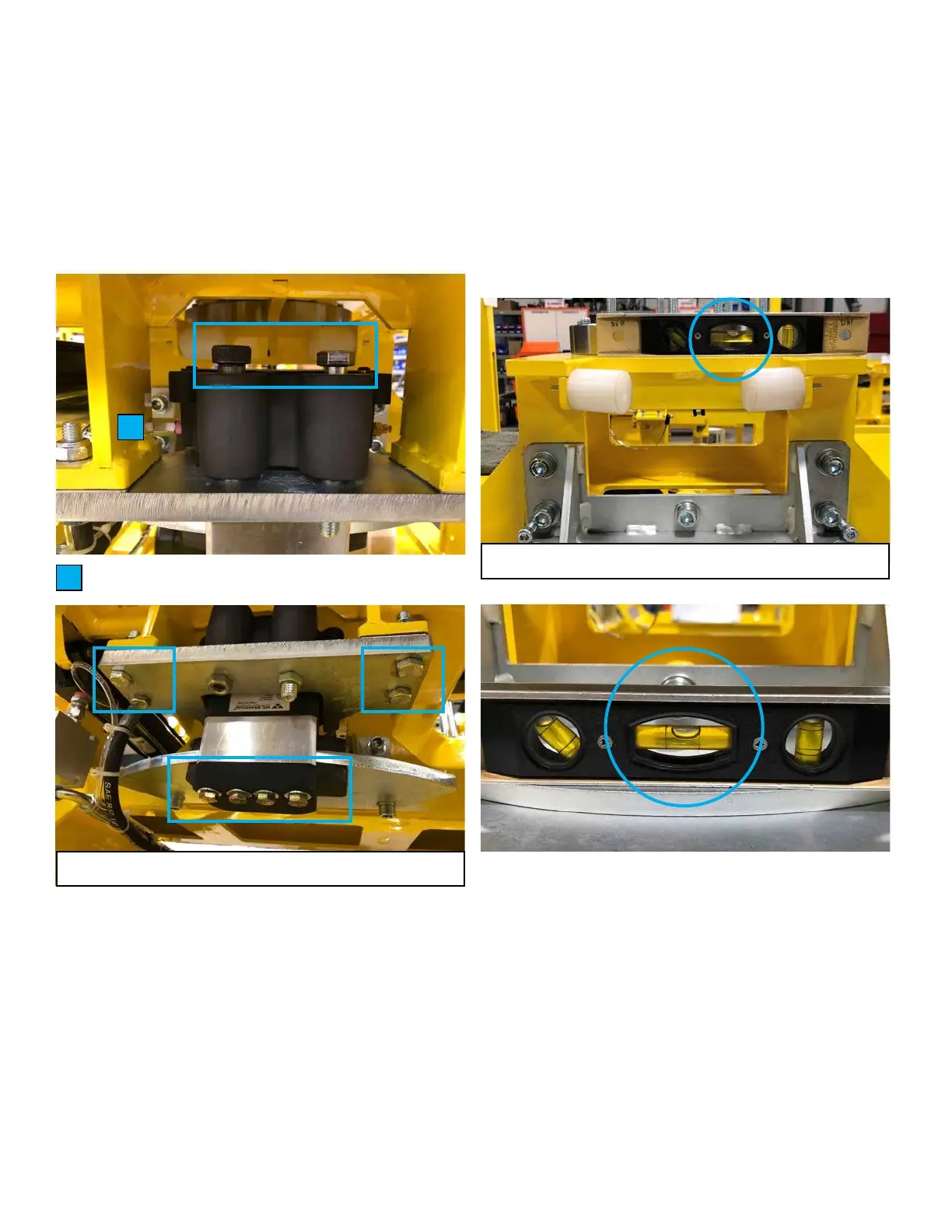
8. Brake Disc Alignment/Setup
IMPORTANT: In order for the new brake to obtain a long
service life, the correct set up of the brake and brake disc
is critical� The brake disc must be parallel and square to
the weldment it is fastened to� Insure that the four bolts
securing the brake disc to the mounting bracket are tight�
Use a small level to compare that the brake disc is parallel to
the weldment� Rest the level on the top of the frame next to
the pivot bearing� Compare the bubble reading on the level
to that of when it is resting on the brake disc� The bubble
reading should be the same in both positions� This will insure
the brake disc is parallel relative to the weldment frame it is
attached to. If they are not parallel, loosen and adjust the ve
mounting bolts until they are�
9� The brake disc must also be square to the machine frame�
Once the disc is parallel, use a machine square to check that
the disc is 90 degrees to the frame� Check both left and right
sides with the square� If it is not square, slightly loosen the
ve-brake disc mounting bolts, being careful not to undo the
previous adjustments. Use the two jacking bolts to ne tune
the squareness of the two assemblies� Use a light to inspect
for any gaps between the square and metal surfaces� Once
the correct angle is achieved, tighten the ve bolts. Re-check
the brake disc is still parallel and square to the frame� These
adjustments must be exactly right for the brake to obtain a
long service life� Once all adjustments have been made and
rechecked, apply Green wicking Loctite to secure any bolts
that were adjusted�
F
Locations of bolts to be loosened
Both bubble positions must be identical
Hydraulic hose
F