54
860-7200-18 DTU DTB Service & Maintenance Manual
REPLACING THE HYDRAULIC BRAKE
IMPORTANT: Only persons who are appropriately trained and
qualied with the safe operation and service of this machine
should be allowed to carry out operation, installation, service or
maintenance� Trained personnel must follow all applicable codes,
laws and standards, both national and local, when conducting
any servicing or maintaining of the machine and associated
equipment� Trained personnel should know and follow all national
and local regulations regarding occupational health and safety
acts or regulations� These persons must also have received safety
training to recognize, identify and avoid any hazards involved in
servicing and maintaining the equipment�
Precautions: It is very important not to loosen or remove any of
the brake disk caliper mounting bolts or jacking bolts� For proper
operation of the brake, it’s critical that the caliper disk be perfectly
positioned to the frame� Failure to ensure this is done will cause
damage to the brake. Only adjust these bolts if necessary – (see
Brake Disc Alignment/Setup)
1. Complete Destu-it Safety Lockout Procedures –
Document 860-6000
NOTE: If hydraulic system won’t allow the front conveyor
to raise to insert the safety block – lower it to the lowest,
downward, angled position, so that all the hydraulic pressure
is released from the system�
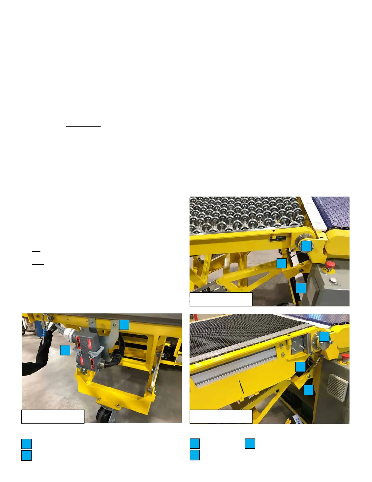
2� Disconnect the main electrical connector and harness
strain relief cable under the rear conveyor� Remove the
bolts securing the connector bracket from the frame of the
conveyor� Reroute the main harness connector out of the
left side of the rear conveyor frame so the plugs can be
reconnected once the rear conveyor section is moved to the
right side� If equipped with a third powered conveyor, any
retainers that hold the third powered conveyor motor wire
to the harness, may have to be removed� This will prevent
damage to the harness and connector while replacing the
brake� Reconnect the main electrical connectors� Unbolt one
end of the ground cable connected to the frame�
3� Remove the white plastic transition plate between the rear
and middle conveyor belts� Support the rear conveyor section
from above (must be sucient to hold the weight). Ideally a
winch or crane should be used as the rear conveyor will need
to be moved sideways somewhat, to allow room to access
the brake� If the rear conveyor cannot be lifted safely, the
brake can still be replaced, but accessing it is more dicult.
If the rear conveyor is non-powered, it can be moved clear
of the machine as it will not have any wiring attached to it�
Remove the four M10 hex bolts securing the rear conveyor
pivot pins (both sides)� Brace the rear conveyor to prevent
damage while removing it� Remove the two rear conveyor
pivot pins from the frame to allow the rear conveyor to
suspend freely� Twist and raise the rear conveyor to release
the two rollers from the slotted tracks underneath, where
the upper portion of the rear conveyor slides on the lower
portion� Once the upper section is free from the lower section,
move it to the right side of the machine and rest it on the
oor or wooden pallet. The third conveyor motor power cable
will restrict the distance that the conveyor assembly can be
moved�
4� Remove the two cotter pins from the clevis pins (both sides)
in the rear conveyor support frame� Support the frame and
remove the two clevis pins� Move the frame away from the
work area�
Main electrical connector and strain relief
Connector bracket mounting bolts
A
B
A
B
C
D
E
Ground strap
Clevis
Pivot pins
C
D
E
C
D
E
Non-powered conveyor
Powered conveyorRear conveyor