51
860-7200-18 DTU DTB Service & Maintenance Manual
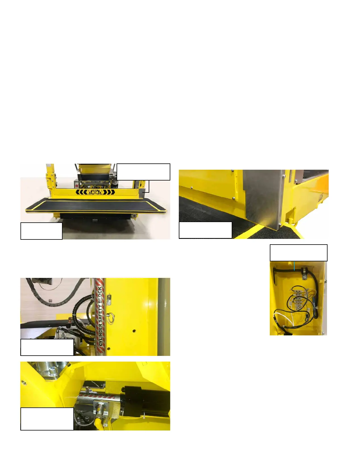
REPLACING THE FRONT SENSING EDGE
STRIP SWITCH
The front sensing edge strip switch is designed to prevent
the machine from travelling forward in the event the Destu-it
machine impacts a person or object in front of it�
IMPORTANT: Only persons who are appropriately trained and
qualied with the safe operation and service of this machine
should be allowed to carry out operation, installation, service or
maintenance� Trained personnel must follow all applicable codes,
laws and standards, both national and local, when conducting
any servicing or maintaining of the machine and associated
equipment� Trained personnel should know and follow all national
and local regulations regarding occupational health and safety
acts or regulations� These persons must also have received
safety training to recognize, identify and avoid any hazards
involved in servicing and maintaining the equipment�
1� Raise the front conveyor and platform to their highest position
o the oor. This will provide access to the underside of the
platform where the cable for the sensing edge is routed�
2. Install the hydraulic cylinder safety block (located on left
side of machine) onto the front conveyor hydraulic cylinder
rod. Insert the pin to prevent it from falling o. Lower the
conveyor until it is resting on the block�
3� Place wood blocking between the oor and underside of
the operator platform� Ideally the platform should be about
12 inches o the oor to allow room to work. Ensure that
the blocking does not obstruct the front or left edge of the
platform where the cable for the sensor edge switch is
routed�
4. Follow the remaining steps detailed in the Destu-
it Safety Lockout Procedure bulletin DT-SB 19-004
to eliminate all potential hazards while servicing the
machine.
5� On the bottom of the left mast (side with conveyor motors
on it), remove the three screws and the cover plate� The
connections for the front sensing edge switch and platform
mat are contained within the cavity� A terminal strip is used
to connect the wires from the sensing edge switch to the
PLC circuits� Using the machine schematics, identify the
two labeled circuit wires for the platform sensing edge/bump
switch and remove them from the terminal strip� Remove the
switch side of the wires, not the corresponding wires which
go to the PLC. Cut any ferrules o the two wires to allow
them to be shed out through the conduit.
6� Tightly tape a long 4-foot sh
wire to the two wires going to the
sensing edge� Be sure to tape the
sh wire smoothly and securely
to the wires to prevent it from
snagging in the conduit during
removal�
7� Starting at the right side of the
platform, carefully use a at
head screwdriver to pry the
rubber portion of the sensing
edge out of the locking groove
in the aluminum channel� Do not
damage the aluminum channel as
it will remain unless it has been damaged� Release either the
top or bottom edge rst and the other should come out easily.
Continue working across to the other side of the edge strip
to fully release the rubber strip� Once the sensing edge strip
edge is fully removed, gently pull the wires attached to the
end of the strip and guide them and the sh wire out through
the conduit located on the underside of the operator platform�
Pull the wires until the sh wire is exposed. Un-tape the sh
wire�
8� If the aluminum extrusion which holds the sensing edge
strip in place is damaged or loose, replace it or any of the
ten screws that secure it� Use Loctite to secure any screws
that need replacing� Clean the channel in the aluminum with
a suitable cleaner/solvent which does not leave any oily
Safety Block
(stored on machine)
Safety Block
(installed on
hydraulic rod)
Platform Box
(left side of machine)
Platform Box
Cover Plate
Raised Platform
(for access)
Terminal Strip