31
860-7200-18 DTU DTB Service & Maintenance Manual
HYDRAULIC SYSTEM
The hydraulic system of the Destu-it is comprised of a hydraulic
pump/power unit, hydraulic manifold with solenoid valves and
pressure regulators, a hydraulic cylinder for the operator platform,
a hydraulic cylinder for the front conveyor and a hydraulic brake�
The hydraulic system is only operational when the Destu-it is
connected to 3 phase AC voltage. The hydraulic uid contained
in the system is ISO VG-46AW. It is recommended to change the
hydraulic uid and tank lter every 2,000 hours (as read o hour
gauge on machine). The volume of uid used in the entire system
is 5 liters. The uid level should be 1-1/2 inches from the top of the
tank when the front conveyor is in the lowest position�
Hydraulic Pump
The hydraulic pump is located under the center of the machine
below the large yellow metal guard containing an ELS logo� There
is a reservoir tank attached to the pump with an internal suction
lter. The output pressure of the pump is preset during production
and should not be adjusted� The pump is powered by 3 phase,
480VAC. Each phase is fused independently. There are two uid
vent lines (one from each cylinder) that connect to the tank�
Manifold
The manifold is located rearwards of the hydraulic pump in the
Destu-it base, under the middle conveyor section. The manifold
has two pressure regulators and two gauges� One regulator is
for the main pressure output to the manifold (1200 psi) and the
other one is for the brake (200 psi)� The two gauges indicate
pump output pressure and output pressure to the brake� The
manifold also incorporates six solenoid valves controlled by the
PLC (labeled SV1 – SV6). These solenoids control the ow of uid
to the cylinders and brake for platform up/down, front conveyor
up/down and brake/brake hold� When a solenoid is activated by
the PLC, a light on the coil wire on top of the solenoid turns ON�
The SV1 solenoid has a Red pushbutton on the top, which if
necessary, will manually open the valve manually and allow the
operator platform to lower if the red button is pushed� This should
only be used if a severe fault in the hydraulic system occurs� The
SV1 and SV2 valves are 2-way, normally closed and won’t allow
uid to ow unless their coils are activated by the PLC. The SV3,
SV4 and SV5 valves are a 3-way type which control ow. The
SV6 valve is a 2-way, normally open valve and allows uid to ow
back into the reservoir unless it’s coil is activated by the PLC�
When SV3 (platform UP), SV4
(Conveyor UP) and SV5 (brake
OPENS) are activated, pump
pressure is supplied to that
component�
Conveyor Hydraulic Cylinder
There are two dierent cylinders
used in the Destu-it machine.
One cylinder is inside the left
mast and raises the platform�
It has a 10-inch stroke. The
platform lowers by gravity
when the SV1 solenoid valve
is activated/opens� The other
cylinder is located on the left
side of the Destu-it below the
middle conveyor� The cylinder
raises the front conveyor� It
has a 9.75-inch stroke. The
front conveyor will lower via
gravity, when SV2 is activated
and allows uid to return to the tank. Each cylinder has its own
dierent, ow control valve located close to the cylinder.
Hydraulic Brake
The hydraulic brake controls the side to side pivot action of the
front conveyor� The brake is located under the middle conveyor�
The brake is normally applied so the front conveyor cannot be
moved from side to side� There is a switch on the left mast which
if turned ON, commands the PLC to momentarily activate SV5 to
release the brake and then activate SV6 continuously, allowing
the front conveyor to pivot� The brake is also released every time
the rotary control hand present sensor is activated (place hand
around the rotary handle)� Valve SV5 is activated and pressurizes
the brake which releases the pads clamping on the brake disc�
The brake disc is xed precisely in place on the machine’s frame
and should not be adjusted. There are two dierent bolts which
the brake caliper slides up and down on� This is a normal design
feature�
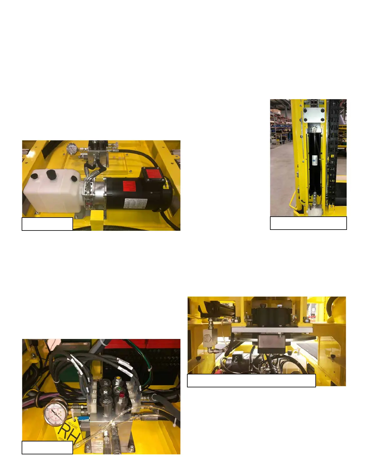
Hydraulic Pump
Hydraulic Cylinder and Hyraulic Brake
Hydraulic Platform Cylinder
Hydraulic Manifold