19
860-7200-18 DTU DTB Service & Maintenance Manual
10� Stand on the operator platform� Press the Green Start button
on the side of the front pivoting conveyor� Wait for 20 seconds
until the PLC starts�
11� Remove Hydraulic Lockout: Use the rotary handle control
to raise the front conveyor to its highest position� Remove
the pin from the safety block and slide the safety block o the
hydraulic cylinder rod� Return the safety block to its stored
position on the side of the machine� Run the front conveyor/
operator platform fully up and down for a few minutes to
bleed o any air in the system.
The Destu-it machine can now be returned to operational
status.
NOTE: In the event of an electrical fast transient burst or surge the
system will protect itself by safely shutting down the machine� For the
standard restart procedure, see Document - DTU / DTB Operation
Manual: “Start-up Sequence”.
It is now safe to service the Destu-it machine.
REMOVING THE LOCKOUTS
Check that all guards have been re-installed and there are no
tools left on the machine� Ensure all personnel are clear from the
machine�
1� The lockout and tag on the main electrical connector at the
rear of the Destu-it can be removed and the connectors
plugged in. Reconnect the Destu-it to any other conveyor, if
it was separated from it�
2� Remove the lockout and tag from the AC cord for the battery
charger�
3� Remove the lockout and tag from the DC disconnect switch�
4� Remove the lockout and tag from the Remote section Power
Drop connector or the Meltric connector if equipped� Plug the
connectors together�
5� Remove the lockout and tag from the switch for the building’s
power supply to the Destu-it machine power drop. Turn the
switch ON�
6� Start the Destu-it machine: Release all 5 E-stops (rotate
clockwise) - 4 on Destu-it and 1 on Remote Panel
7� At the Drive Panel, turn ON the AC disconnect switch and the
DC disconnect switch�
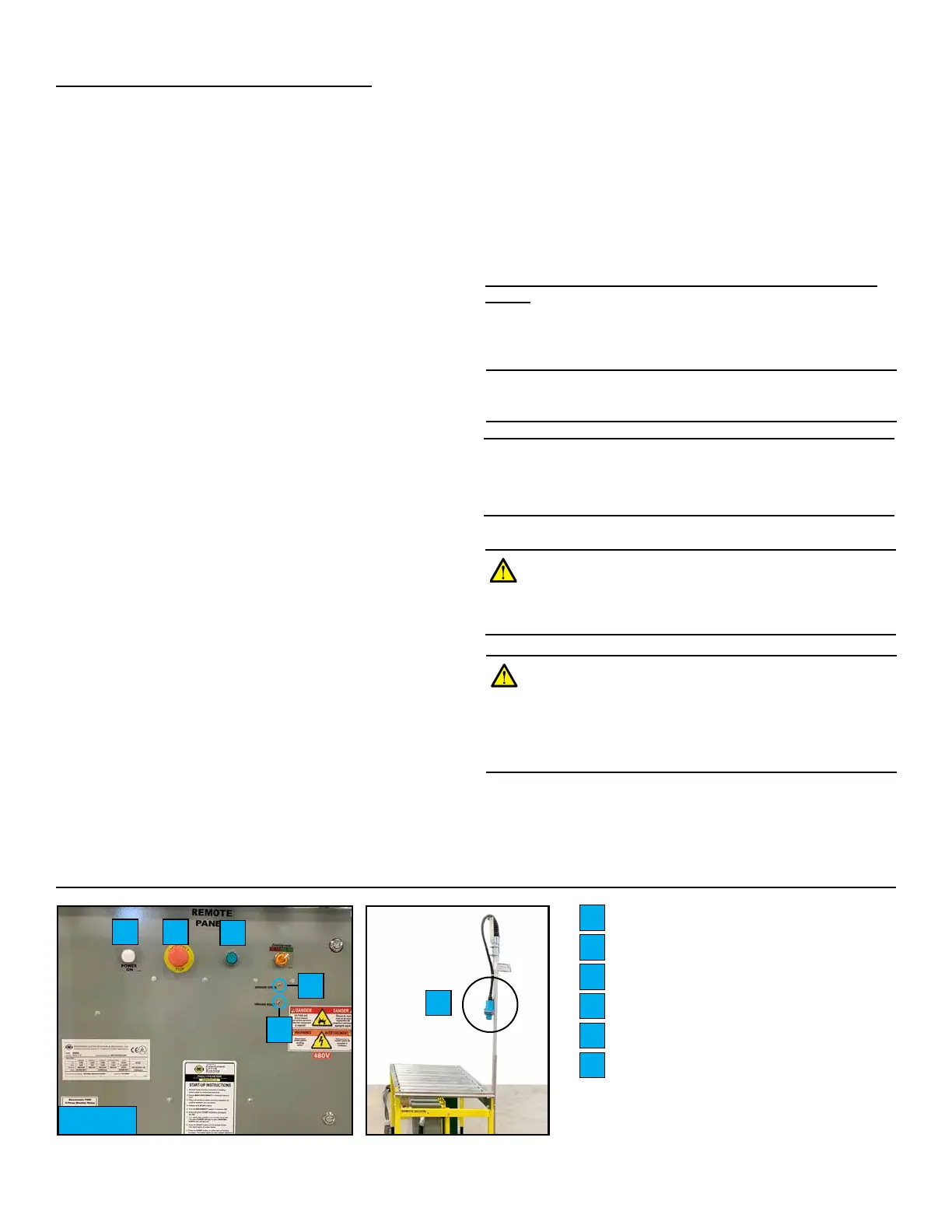
8� Turn on the AC disconnect switch on the Remote Panel
(Fig� 11) or plug in the Meltric connector (if equipped)� The
White “Power ON” light will illuminate if power is present� If
cable connections are OK, the small Green “Ground Check”
LED indicator will be illuminated� If “Ground Fault” Red LED
at remote panel is ON, there is a ground fault which must be
corrected before proceeding� The Green LED must be ON or
the system will not run�
9� Press the Green Start button on the Remote Panel� If supply
power phasing is OK, start button remains illuminated Green�
NOTE: If your machine has network integration, the Remote Panels will
appear dierent. Please see Appendix.
White Power ON Light
E-Stop Button
Green START Button
Ground Fault Red LED
Ground Check Green LED
Meltric Connector
A
B
C
D
E
F
F
A B
C
D
E
Fig. 11
REMOTE PANEL (FRONT)
WARNING: Disconnect ALL power before servicing�
Multiple power sources may be present� Failure to do so
may cause property damage, personal injury or death�
RESIDUAL POWER REMAINS IN BATTERIES.
WARNING: Do not disconnect the power and signal
connectors between the conveyor belts and the Restu-it
while the unit is energized� Multiple power sources may
be present� Failure to do so may cause property damage,
personal injury or death� RESIDUAL POWER REMAINS
IN BATTERIES.