24
860-7200-18 DTU DTB Service & Maintenance Manual
120VAC Circuits
There is more than one 120VAC circuit in the Destu-it machine.
Some systems use 120VAC to power ex conveyors attached
to the Destu-it. These are powered by one or more step down
transformers usually mounted on the Remote Section of the ma-
chine. These transformers utilize the 3 phase – 480V power from
the building and convert it to 120VAC� The transformer power
inputs are fused individually in the Remote Panel� The 120VAC
output is connected to a ex conveyor integration circuit which
ELS designs and is integrated into the ex conveyor’s control and
power circuits�
The other 120VAC circuits are for an E-Stop circuit, some Destu-
it control circuits and to power the battery charger. There is a step-
down transformer located in the base of the machine at the rear,
next to the batteries and another one in the Remote Panel�
480VAC Circuits
The Destu-it uses 3-phase, 480VAC for running the Destu-it
conveyor VFDs and drive motors and the hydraulic pump� Each
of the three lines is fused in the remote panel� These circuits are
monitored by a ground fault monitor and phase monitoring devic-
es� If a problem is detected by these modules the machine will not
start or run� There is an AC disconnect switch on the Drive panel�
There is an AC/DC selector switch on the top of the left-hand post.
ELECTRICAL SYSTEMS
The Destu-it machine uses 3 electrical systems: 24VDC,
120VAC and 3 Phase - 480VAC.
24VDC Circuits
The Destu-it machine contains two maintenance free, 12-volt
AGM batteries wired in series to power the drive system and PLC
control circuits with 24VDC� There is an AC charger in the base of
the machine, which charges and maintains the charge on the bat-
teries� When the machine is operating on AC power, the battery
charger maintains the batteries� When the machine is discon-
nected from the buildings AC power supply and is turned OFF, the
battery charger should be plugged into a 120VAC outlet to main-
tain the batteries� There is a power cord connector at the back of
the Destu-it for this. The battery charger regulates the batteries
independently� The battery charger has separate indicator lights
for settings, diagnostics and charge status�
The machine will have either the XANTREX
®
Battery Charger or
the NOCO
®
Battery Charger installed, depending on which was
provided�
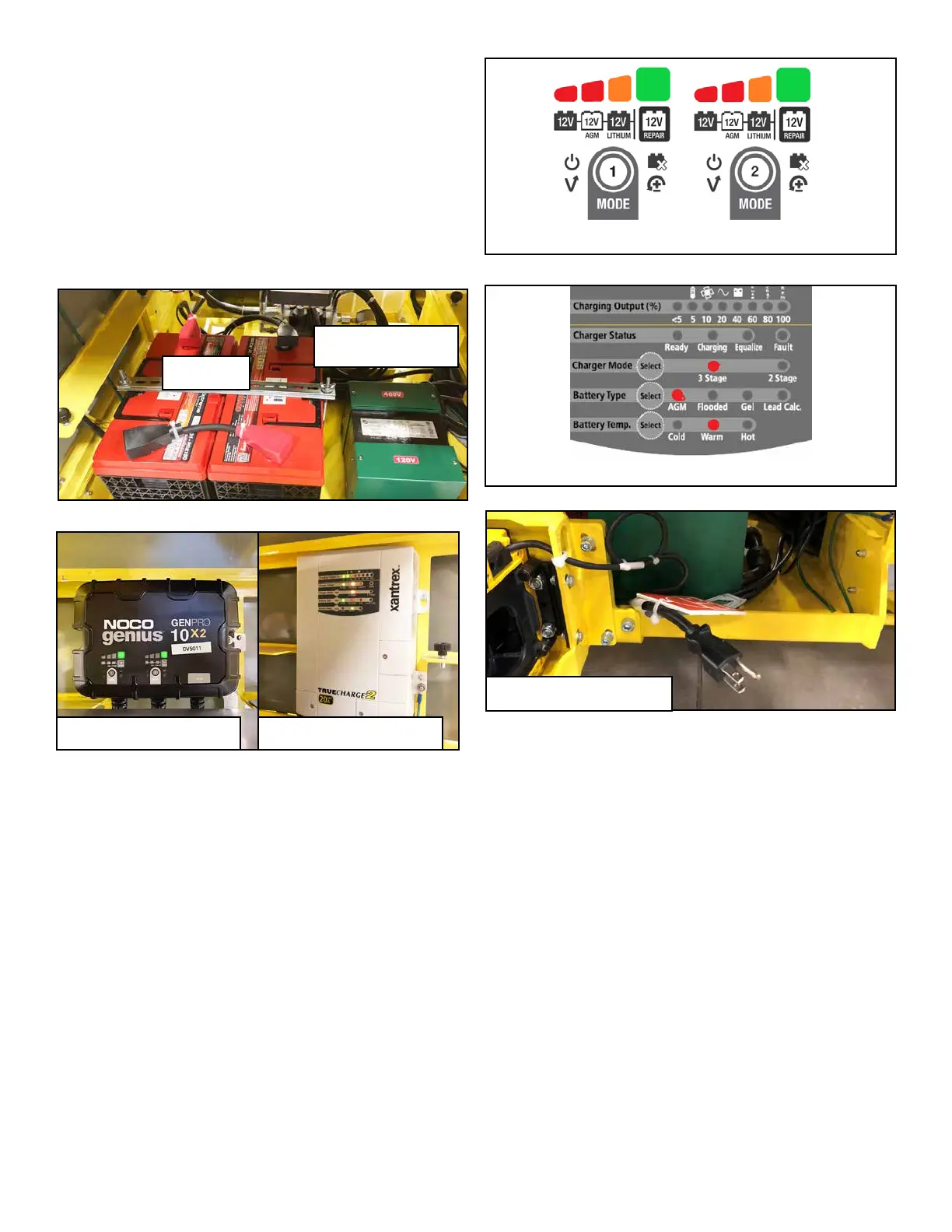
For the NOCO
®
Battery Charger, the charger must be set to 12
AGM mode� For the XANTREX
®
Battery Charger, the settings are
preset at the factory and should not be changed from Warm, AGM
and 3 Stage�
There is a timer circuit built into the machine’s control system that
will automatically shut the machine o after six minutes of inactiv-
ity to prolong the life of the batteries� The batteries can also be
disconnected from the system through the use of the DC discon-
nect switch on the Drive panel�
NOTE: Refer to the NOCO
®
Genius
®
GENPRO Series User
Manual or the Xantrex
®
Truecharge2 Battery Charger Owners
Guide for detailed instructions and fault codes.
AC Cord for Battery Charger
Batteries
Transformer
(480VAC to 120VAC)
NOCO
®
Battery Charger
NOCO
®
Battery Charger settings window
XANTREX
®
Battery Charger
XANTREX
®
Battery Charger settings window