52
860-7200-18 DTU DTB Service & Maintenance Manual
residue or coating� DO NOT spray lubricant in the channel�
This won’t allow the new sensor strip to stay rmly in the
channel, once it is installed�
9� Tightly tape the end of the new sensing edge wires to the sh
wire protruding from the hole in the front of the platform and
pull them back through the conduit and into the platform box�
Remove the tape and sh wire from the end of the wire, once
it is fully routed into the platform box�
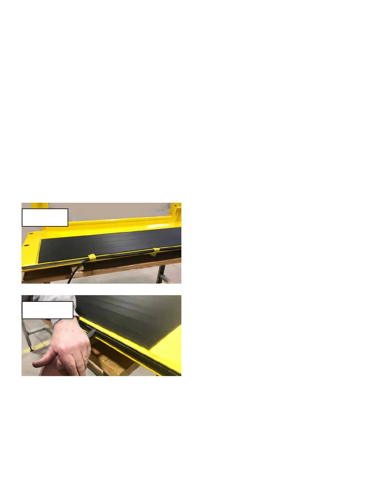
10� Use tape to loosely support the length of the sensing strip
along the front edge of the platform� This will prevent the
strip from falling downwards as the strip is inserted into the
aluminum channel� Starting at the left side of the platform
(side with platform box), feed about 4 inches of the bottom
edge of the new sensing edge strip into the bottom groove of
the aluminum channel. Using a nger or a plastic edged tool,
rmly but gently push the top edge of the strip into the top
groove in the channel� DO NOT use a metal screwdriver as
it may damage the sensor strip� Push it down and then back
to slide under the top groove edge in the channel� Continue
working a portion of the bottom into place, followed by the top
edge� Avoid stretching the rubber strip as it is inserted, so as
to prevent it from overhanging the far edge of the channel or
platform side� The sensing strip should be even side to side
inside the aluminum channel when it is completely installed�
11� Inspect the strip once it is installed to ensure that the entire
length is evenly tucked into the upper and lower grooves of
the aluminum channel and is even side to side�
12� Cut the two wires in the platform box from the new sensor
strip to length, leaving enough wire to reconnect them�
13� Connect the two wires to the terminal strip ports that the
wires were removed from earlier� If possible, label the new
switch wires with their corresponding circuit numbers for
future service identication. Crimp ferrules onto the ends of
both wires� Insert each ferrule back into one, or the other
terminal strip ports they were removed from earlier� It makes
no dierence which wire goes to either of the two respective
terminal ports so long as one wire is connected to each port
and is labeled accordingly�
14� Re-install the platform box cover using the three M5 screws.
15� Inspect the work and verify that everything has been done
correctly� Reverse the lockout/tagout procedure� See
document DT-SB 19-004 for instructions� Remove the wood
blocking from under the operator platform�
16. TESTING: Place a suitable solid obstacle in front of the
operator platform to simulate a person or box, to test the
functionality of the sensing edge as the Destu-it is driven
forward� DO NOT use a hard-xed obstacle or damage can
result to the new switch� The machine should stop and the
beeper will sound continually if the sensor edge contacts a
stationary object� Drive the machine in reverse to reset the
safety measure and allow the machine to operate normally�
TROUBLESHOOTING:
The Destu-it/Restu-it does not stop and sound the warning
beeper when front sensing edge is pressed while moving
forward.
1� Use the machine schematics to test the “bump strip”
(Sensing edge switch) fuse for 24 volts� Replace the fuse
if blown. If the fuse tests good - remove the cover over the
platform box� The front sensing edge strip is a simple switch
which closes the contacts upon a rm press anywhere along
the length of the rubber strip. Using a digital meter conrm
that only one of the two sensor strip wires reads 24 volts +.
The other wire should read at or near 0 volts� Firmly press
the front edge of the sensor strip while measuring the voltage
on the second (0 volt) sensor strip wire� The wire should now
read 24 volts and go back to 0 volts when the front edge of
the sensor strip is released�
2� If the fuse is good and reads 24 volts+ on both wires from
the sensor switch, disconnect the switch wires in the platform
box coming from the switch and measure the resistance
across the two wires. It should read open or innite at rest
and less than 1 ohm while pressing on the sensor edge� If
the switch tests OK, check the wire harness from the control
panel to the platform box for short circuits using a volt meter�
The harness is routed from the Control Panel, through a
cable track system on the left post to get to the platform box�
3� If neither of the wires at the terminal strip read 24 volts +, use
a digital meter to test for opens or high resistance in the wire
through the cable track harness from the fused output of the
control panel to the platform box terminal strip�
4� If both wires at the terminal strip read 24 volts + at rest
(nothing pressing on or contacting the rubber strip edge),
disconnect the two wires from the terminal strip� Check for
short circuits between the platform box and the sensor edge
input wire to the PLC in the Control Panel� The circuit should
have near 0 volts�
Support the new
switch with tape.
Press down rmly
with plastic tool.