49
860-7200-18 DTU DTB Service & Maintenance Manual
8� Before joining the new belt ensure that the sprocket spacing
is correct on all three shafts� Some shafts have metal
retaining rings which lock the sprockets in place, on the shaft�
For those machines that do not use metal retaining rings, the
sprockets can slide along the shaft, so they need to be evenly
spaced across the width of the shaft� Some shafts have only
the center sprocket xed in place by metal retaining rings.
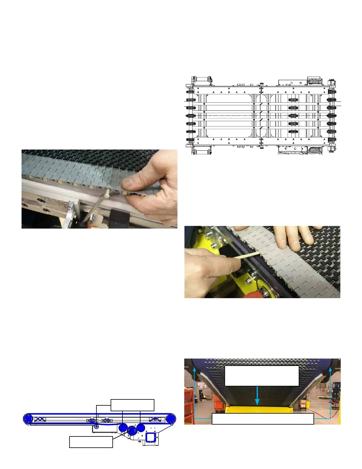
9� Pull both ends of the belt together� As this is being done,
make sure that the underside of the belt is seated properly
in the teeth of the sprockets� The belt should be tight to the
rollers/sprockets when it is pulled together� Ensure the belt
is evenly positioned from side to side. Join the belt by
feeding the rod through each of the belt links� Gently tap the
rod with the handle end of the removal tool, until it seats ush
in place on the outside link�
NOTE: If the two ends of the new belt cannot be pulled
together for the rod to be inserted, review steps 7 & 8� If the
belt has slack under the sprockets on the drive shaft it cannot
be forced or pulled out to resolve this� The belt will have to
be reversed back out by spinning the fan blade and properly
adjusted�
6� Use the rod removal tool (part # H0102262) to partially
remove a rod from the top of the belt� Grab the end of the
rod and pull it completely out of the belt while someone holds
either side of the belt where it is being split� The belt rods
have a head on one side� The belt rods should be installed
from alternating directions� Every second rod should be
inserted from the left side of the belt� Once the belt is split,
have someone grab the rear edge of the belt and hold it
vertically, directly above the tail shaft (rear of front conveyor)�
They will need to slowly feed/lower the belt into the conveyor
as it is removed out of the front of the conveyor frame� Fold
the front edge of the split belt forward� Let it hang down the
towards the oor o the front of the conveyor. Spin the fan
blade on the end of the front conveyor motor� This will slowly
move the conveyor belt forward/reverse� Spin the blade so
the belt moves towards the front of the conveyor� DO NOT
PULL on the belt. This can damage the sprockets� Once the
belt has unwound from the tail and drive shafts it will easily
ow out of the front of the conveyor frame.
NOTE: Once the belt is removed check the interior of the
conveyor for any debris and/or damage to the components
(such as sprockets, wear strips and rollers)� Remove all
debris, dirt and replace any damaged components�
7. Conrm that the new belt is 262 links long. Feed the new
belt into the conveyor from the front� The belt must run on
top of the UHMW guides on the underside of the conveyor
frame� Ensure that it is fed over the idler rollers and around
the drive shaft correctly� It is critical that the belt be held
tight against the underside of the drive shaft sprockets.
Failure to ensure this is done, will not allow the new belt
to be joined back together and will damage the new belt
and sprockets. Once the leading edge of the belt contacts
the drive shaft sprockets, spin the front conveyor motor fan to
rotate the belt around the underside of drive shaft� Use two
people - one on each side of the machine - to hold the belt
tight to the underside of the drive shaft and keep it parallel to
the shaft as one person spins the motor fan blades to engage
the sprockets and belt� Continue to spin the fan blade to reel
in the belt� Route the belt over the rear idler roller and around
the outside of the tail shaft and above the transition plate,
until the end of the belt is halfway down the length of the front
conveyor�
Spacing should be equal side to side
Correct amount of belt sag:
4 mm gap
Drive Shaft
Idler Rollers