42 / 64
33040_mc32exHoTT_V1.00_en
43 / 64
33040_mc32exHoTT_V1.00_en
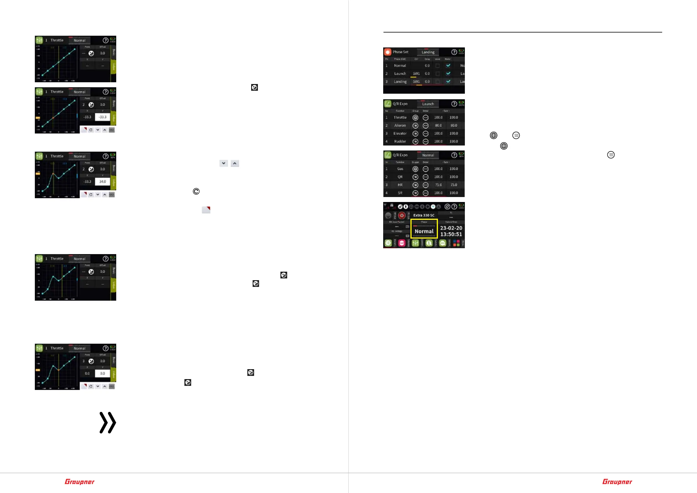
Setting the curve characteristic step-by-step
1. Switch to the „Value“ display page.
2. Bring the vertical green line to the desired point with the rele-
vant control, in the example with the throttle control stick.
The point approached is shown in red.
The number of the point and the symbol
for setting or delet-
ing a point are displayed on the right of the graphic.
Its coordinates are displayed below it, as well as a yellow rect-
angle at the bottom or left edge of the display, depending on
the active coordinate field, and a control panel at the bottom
right of the display.
3. The selected point can now be moved either horizontally or ver-
tically, namely ...
... either by tapping the icons
in steps of 0,1 %.
… or by moving the horizontally or vertically relevant orange
rectangle with a fingertip or a stylus suitable for touch screens.
– Tapping the icon
resets the value of the selected row back
to the default.
– Tapping the symbol
activates „Direct setting“ further set-
tings of this option are to be made in the menu of the same
name of the „orange“ function menu
Add a point step-by-step
1. Use the relevant encoder to move the vertical green line between
two points.
As soon as „---“ are visible to the left of the icon
, another
point can be set by tapping on the icon . Up to three more
points are possible.
2. If needed, adjust the position of the added point as described
above.
3. Proceed in the same way with other points.
Delete point step-by-step
1. Use the appropriate encoder to move the vertical green line to
the point you want to delete.
The selected point is displayed in red and the number of the
point is displayed to the left of the icon
below „Point“.
2. Tapping the icon
deletes the selected point. In the figure on
the left that would be e.g. Point 3.
3. Proceed in the same way with other points.
Note
As soon as a point is added or deleted, the points are auto-
matically recounted from left to right.
Phase Set
During model operation, settings and/or trim positions adapted
to specific operating conditions are often required. In the case of
airplanes, for example, this can also be understood outside of
model flight using terms such as “takeoff phase”, “normal flight
phase” and “landing phase” or “hovering phase” for helicopters,
etc. This is implemented in the Graupner-world as “phase“, called
up by switches and each “phase” is a variant of basic settings of
certain menus. (Maybe known as „Level“ from other RC systems.)
Recognizable in most menus by a column heading or field desig-
nation „Group“ and the associated selection option between the
icons
and .
The icon
stands for „global“, i.e. the relevant settings are valid
for all phases that may be active and the icon for „phase-spe-
cific“, i.e. the respective settings are only valid in the currently acti-
vated phase.
Which phase is currently active can be seen not only in the basic
display, but also at the top of all menus affected by the changing
phase name in the course of switching between phases, see exem-
plary illustrations on the left.
• As long as no other phases are programmed and these switches
are assigned, the transmitter is automatically in phase 1 „Nor-
mal“.
• A maximum of 12 phases are possible.
• If an option is changed from „global“ to „phase-specific“, the
originally „global“ setting is applied to all activated „phases“
and can then be individually adjusted in each active phase.
• If an option is changed from „phase-specific“ to „global“, the
settings of that phase in which the change was made apply
„globally“ after the change.
• Details on the respective setting options can be found in the
context-related help texts in the respective menus.