48 / 64
33040_mc32exHoTT_V1.00_en
49 / 64
33040_mc32exHoTT_V1.00_en
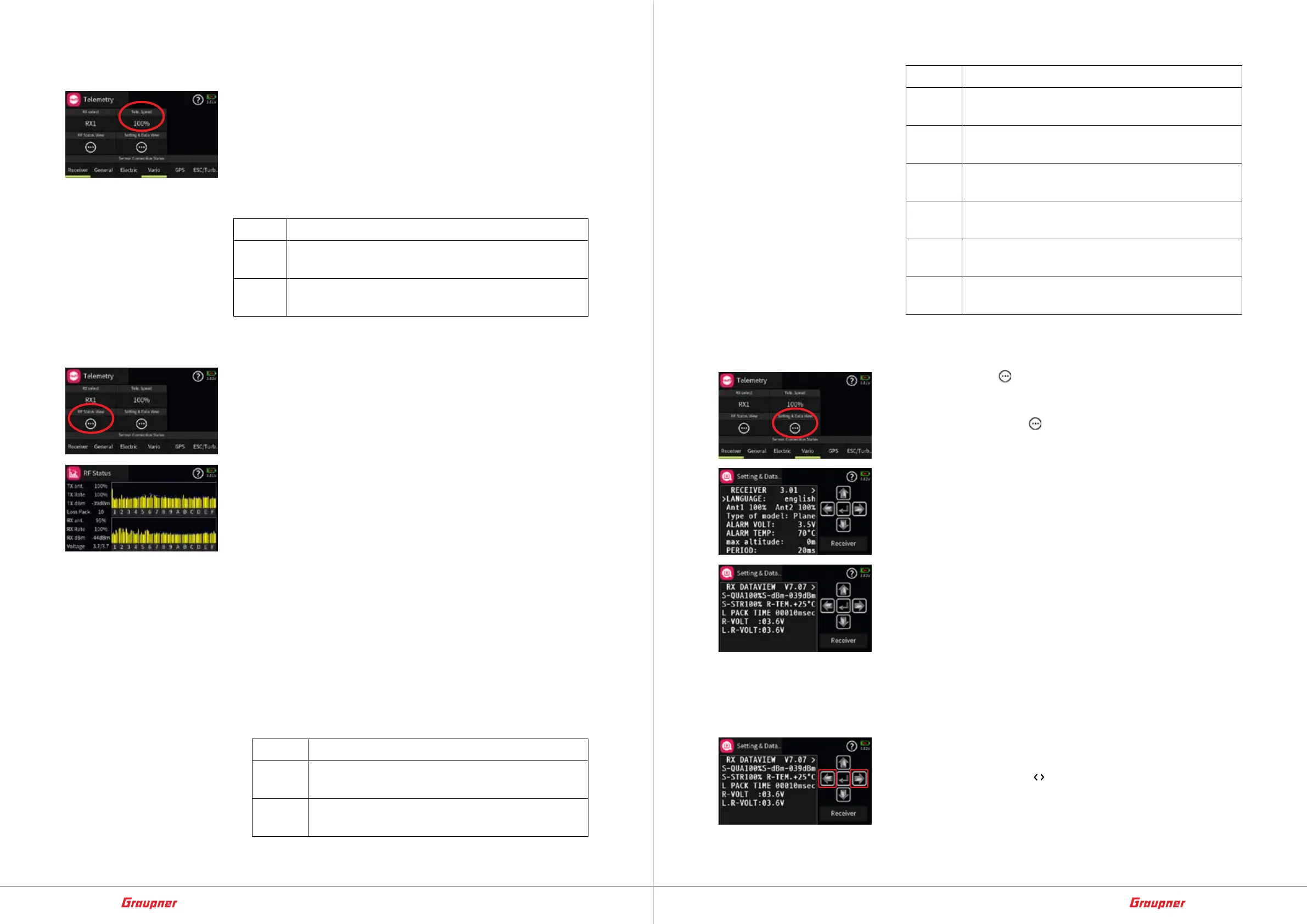
Tele. Speed
Currently, the use of setting that deviates from the standard value
„100%“ is only recommended if two receivers placed relatively
close to each other are each controlled independently of one
another by their own transmitter. So in the case of installation sit-
uations, such as those that can occur with a camera copter with
separate control of camera and copter or with towed models for
model parachutists. In such cases, the return channel can interfere
with the control channel.
Value Description
100 % As default, the transmitter responds to the return
channel of the selected receiver.
50 % /
33 %
The transmitter reacts to the return channel of the
selected receiver with a corresponding delay.
RF Status display
This display visualizes the quality of the connection between trans-
mitter and receiver. If there is no connection to a receiver, the sub-
menu can be opened, but the displays remain empty. If necessary,
switch on your receiving system or switch to the correct receiver.
• Top row
Level of channels 1 ... 75 (US 1...70) of the 2.4 GHz band com-
ing from the receiver in dBm at the transmitter.
• Bottom row
Level of channels 1 ... 75 (US 1...70) of the 2.4 GHz band com-
ing from the transmitter in dBm at the receiver.
Remarks
• The height of the bar is a measure of the respective reception
level, expressed as logarithmic values with the unit dBm (1 mW
= 0 dBm).
• 0 dBm corresponds to the two baselines in the graph, which
means the worse level as the bar goes higher and vice versa.
• The dots above the bar mark the worst reception levels from
the opening of the „RF Status“ display. A reset of these points
is therefore possible by exiting and recalling this display.
• In addition to the graphic display of the reception level, addi-
tional numeric information is provided to the left. This means:
Value Description
Tx ant. Strength in % of the receiver‘s signal packets
arriving at the transmitter
Tx Rate Quality in % of the receiver ‘s signal packets
arriving at the transmitter
Value Description
Tx dBm Level in dBm of the receiver signal arriving at the
transmitter.
Loss
Pack.
Indicates the number of lost data packets.
Rx ant. Quality in percentage of the signal packages
from the transmitter arriving at the receiver.
Rx Rate Quality by a percentage of the signal packages
from the receiver arriving at the transmitter.
Rx dBm Level in dBm expressed as the percentage of the
transmitter signal arriving at the receiver.
Voltage Actual operating voltage of the power supply of
the receiving system.
Setting & Data View
Tapping the symbol opens the “Settings & Displays” display. If
none of the named devices is highlighted with a green bar in the
bottom line of the display and the display window remains empty
after tapping the symbol
, there is no connection to a corre-
sponding device. If necessary, switch on your receiving system or
switch to the correct receiver or device.
• A detailed description of the submenus of standard receivers
such as the Graupner GR-12 or GR-16 can be found in
downloadable version of these receivers‘ instructions at
www.graupner.com but also in the instructions of the vari-
ous other hand-held and console transmitters with displays in
the Graupner-range. Except for the slightly different visual
appearance of the Graupner mc-32ex HoTT transmitter dis-
play and the operation described below, all of these descrip-
tions can be transferred 1:1 to this transmitter.
• Specialty receivers such as the receiver Graupner Hawk 18
HoTT (Order.-No. S1053), as well as sensors, etc. are equipped
with independent variants of the „Settings & Displays“ menu.
The description of these special submenus can be found in the
respective manual.
Function of the cross-shaped keypad
• left and right selection keys
Similar to the directional arrow in the upper right corner of the
framed display section (
), you can use the right or left button
to switch between the individual pages of the respective sub-
menus of the „Settings & Displays“ menu.