D-6 BOOST LIMITER CUT
49
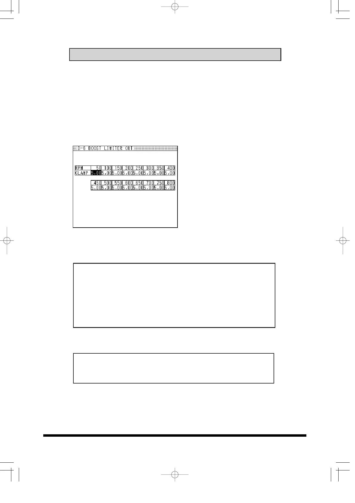
Boost Limiter Cut Setting
• This is used to eliminate the factory fuel cut by ECU due to the
increase of the intake air flow.
• The Air Flow Meter or MAP sensor input signal to the ECU can be
clamped. However, since ECU can not recognize the amount of
increase of the intake air flow over the clamped signal,
compensation (increased fuel) in the Additional Injector Map is
recommended.
1. In the data recording
feature, record the rpm
point and air flow
meter/MAP sensor voltage
and injector duty cycle
where the boost limit
occurred.
2. Input the clamping value.
Input a value slightly lower
than the point where
injector duty cycle becomes
0% in the data.
rpm:
Input range: 0 ~ 10000rpm, 100rpm increments
Clamp Value: This will automatically change according to the
sensor type.
Input range: 0 ~ 5V, 0.05V increments (Air Flow, or MAP type:V)
Input range: 0 ~ 3150Hz, 50Hz increments (Karman type :Hz)
• This feature is not used for the vehicles that does not have a
boost limiter.