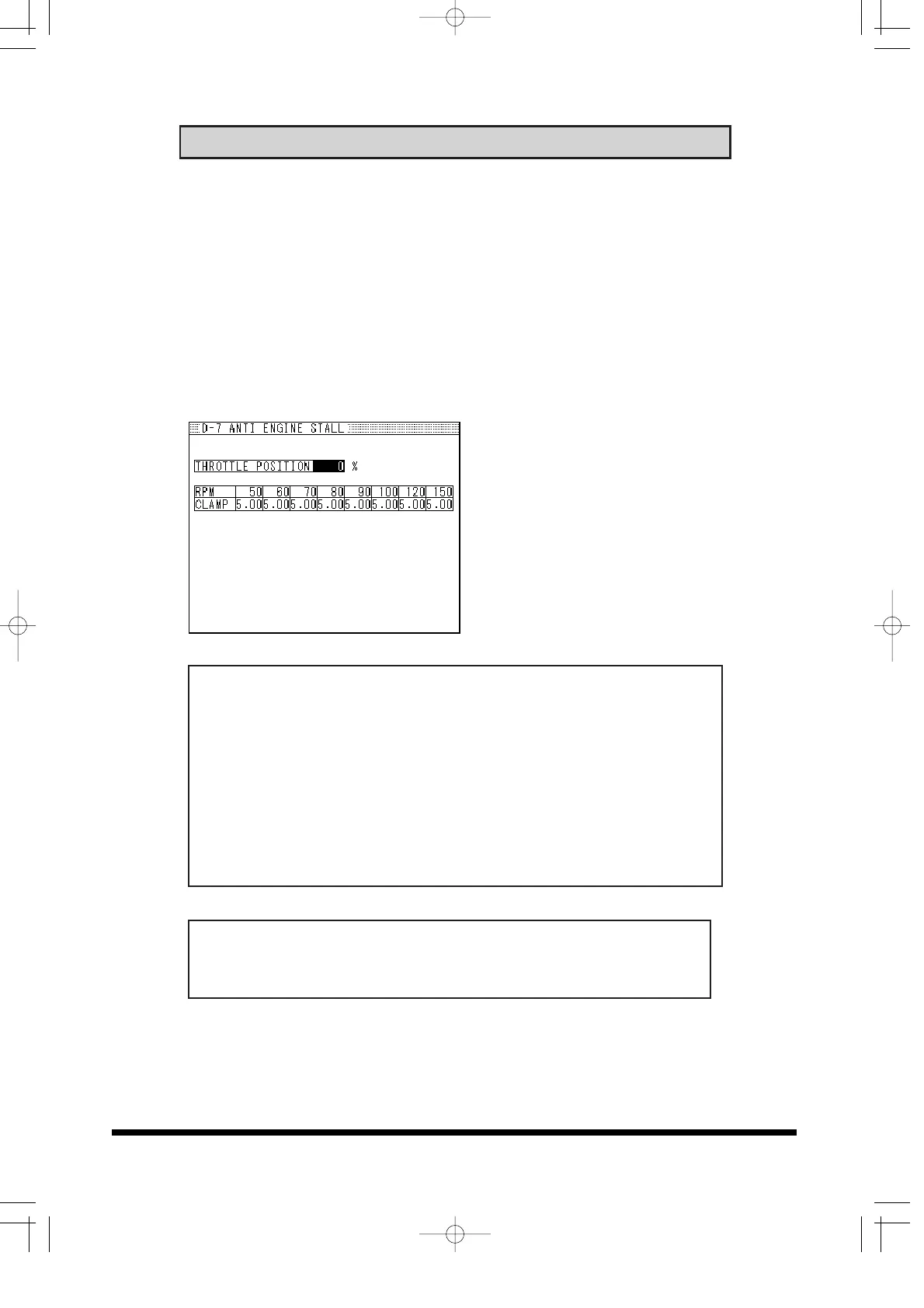
D-7 ANTI ENGINE STALL
50
Anti Engine Stall Setting
• This feature is used to stabilize the rough idle due to the turbo
compressor surge, blow-off valve vented out to the atmosphere or
use of a high lift camshaft.
• Input the Throttle Position in degrees. This will allow the values
below the inputted value (throttle opening) to be recognized as
accelerator OFF (fully closed).
• The Airflow Meter or MAP sensor input signal to the ECU can be
clamped at a desired voltage at 8 different rpm points to prevent
engine stall or rough idle.
1. In the data record feature,
record the rpm point, airflow
meter/MAP sensor voltage
and injector duty cycle where
the engine stalls.
2. Input the rpm points where
the airflow voltage fluctuates
and input the airflow
clamping value.
Throttle Position: %
Input range : 0 ~ 10%, 1% increments
rpm:
Input range: 0 ~ 8000rpm, 50rpm increments
Clamp Value: This will automatically change according to the
airflow type.
Input range: 0 ~ 5V, 0.05V increments (Air Flow, or MAP type:V)
Input range: 0 ~ 3150Hz, 50Hz increments (Karman type :Hz)
• This feature is not needed for vehicles that do not have any
engine stalling problems.