59
11.8 Data communication
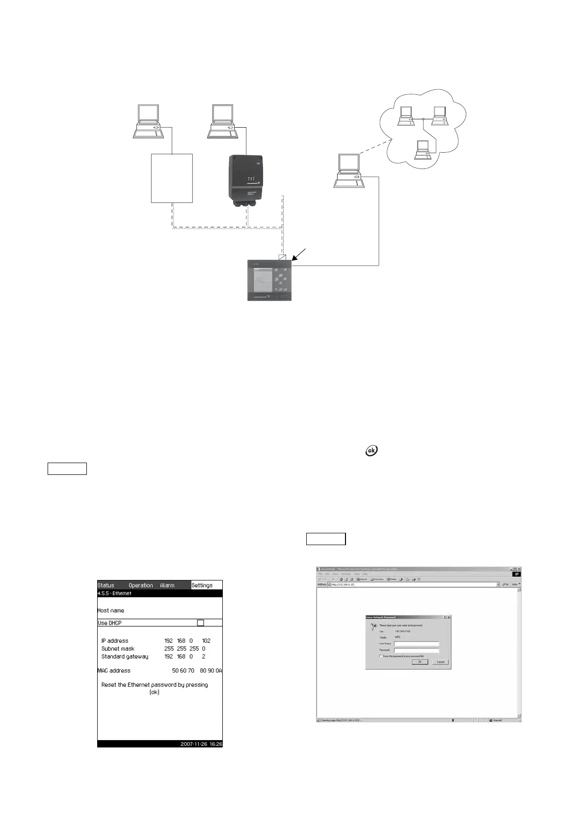
CU 351 is equipped with a hardware enabling communication
with external units, such as a computer, via an external GENIbus
or Ethernet connection.
Fig. 107 Data communication via external GENIbus and Ethernet connection
11.8.1 Ethernet
Ethernet is the most widely used standard for local networks
(LAN). The standardisation of this technology has created some
of the easiest and cheapest ways of creating communication
between electrical units, for instance between computers or
between computers and control units.
The web server of the CU 351 makes it possible to connect a
computer to the CU 351 via an Ethernet connection. The user
interface can thus be exported from the CU 351 to a computer so
that the CU 351 and consequently the system can be monitored
and controlled externally.
In order to use the web server, you must know the IP address of
the CU 351. All network units must have a unique IP address in
order to communicate with each other. The IP address of the
CU 351 from factory is 192.168.0.102.
Alternatively to the factory-set IP address, it is possible to use a
dynamic assignment of IP address. This is possible by activating
a DHCP (Dynamic Host Configuration Protocol) either directly in
the CU 351 or via the web server. See the example in fig. 108.
Fig. 108 Example of setting of Ethernet
Dynamic assignment of an IP address for the CU 351 requires a
DHCP server in the network. The DHCP server assigns a number
of IP addresses to the electrical units and makes sure that two
units do not receive the same IP address.
A traditional Internet browser is used for connection to the web
server of the CU 351.
If you want to use the factory-set IP address, no changes are
required in the display. Open the Internet browser and enter the
IP address of the CU 351.
In order to use dynamic assignment, the function must be
activated. Click Use DHCP in the menu line. A check mark
next to the menu line shows that activation has been made.
After activation in the display, open the Internet and enter the
host name of the CU 351 instead of the IP address. The Internet
browser will now try to connect to the CU 351. The host name can
be read in the display, but can only be changed by either a GSC-
file (configuration file) or via a web server. See Change of
network setting on page 60.
This is the first display shown when connecting to the CU 351.
Fig. 109 Connection to CU 351
TM03 2044 1009
Intranet
Internet
External GENIbus connection
Ethernet connection
External
GENIbus module
(factory option)
Grundfos CIU
communication
interface
Third-
party
gateway
Grundfos recommends that you protect the
connection to the CU 351 according to your
safety requirements in consultation with the
system administrator.
TM03 2298 4807
To use DHCP, a host name is required.
TM03 2048 3505