English (GB)
11
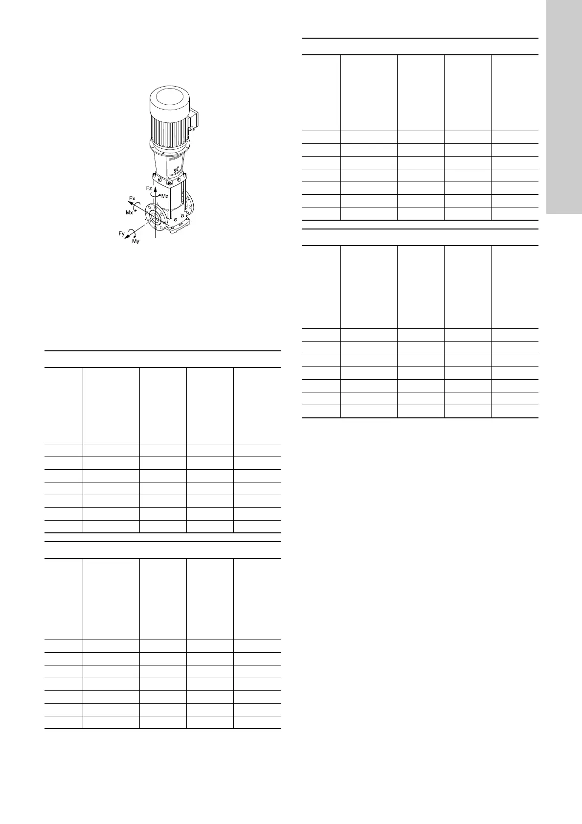
6.6 Flange forces and torques
If not all loads reach the maximum permissible value stated in the
tables below, one of these values may exceed the normal limit.
Contact Grundfos for further information.
Fig. 14 Flange forces and torques
Forces
The following tables represent values that applies according to
the material quality.
TM04 0346 2013
Y-direction: Inlet/outlet
Z-direction: Direction of chamber stack
X-direction: 90 ° from inlet/outlet
Force limits for CR cast-iron pump housing
Flange, DN
[mm]
CR
Force, Y-direction
[N]
Force, Z-direction
[N]
Force, X-direction
[N]
25/32 1s-5 338 394 319
40 10 413 469 375
50 15 and 20 563 581 506
65 32 694 788 638
80 45 938 769 844
100 64 and 90 1256 1013 1125
125/150 120 and 150 1256 1013 1125
Torque limits to CR cast-iron pump housing
Flange, DN
[mm]
CR
Torque, Y-direction
[Nm]
Torque, Z-direction
[Nm]
Torque, X-direction
[Nm]
25/32 1s-5 300 175 125
40 10 400 275 200
50 15 and 20 450 325 250
65 32 500 350 300
80 45 325 400 550
100 64 and 90 375 475 625
125/150 120 and 150 375 475 625
Force limits for CRI, CRN stainless-steel pumps housing
Flange, DN
[mm]
CRI, CRN
Force, Y-direction
[N]
Force, Z-direction
[N]
Force, X-direction
[N]
25/32 1s-5 675 788 638
40 10 825 938 750
50 15 and 20 1125 1163 1013
65 32 1388 1575 1275
80 45 1875 1538 1688
100 64 and 90 2513 2025 2250
125/150 120 and 150 2513 2025 2250
Torque limits to CRI, CRN stainless steel pump housing
Flange, DN
[mm]
CRI, CRN
Torque, Y-direction
[Nm]
Torque, Z-direction
[Nm]
Torque, X-direction
[Nm]
25/32 1s-5 600 350 250
40 10 800 550 400
50 15 and 20 900 650 500
65 32 1000 700 600
80 45 650 800 1100
100 64 and 90 750 950 1250
125/150 120 and 150 750 950 1250
 Loading...


