English (GB)
12
7. Electrical connection
The electrical connection must be carried out by an authorised
electrician in accordance with local regulations.
The operating voltage and frequency are marked on the motor
nameplate. Make sure that the motor is suitable for the power
supply on which it will be used and the motor terminal connection
is correct. You will find a wiring diagram in the terminal box.
7.1 Cable entry/screwed connection
All motors are supplied without screwed cable entries. The table
below shows the numbers and sizes of cable entry holes of the
terminal box (standard EN 50262).
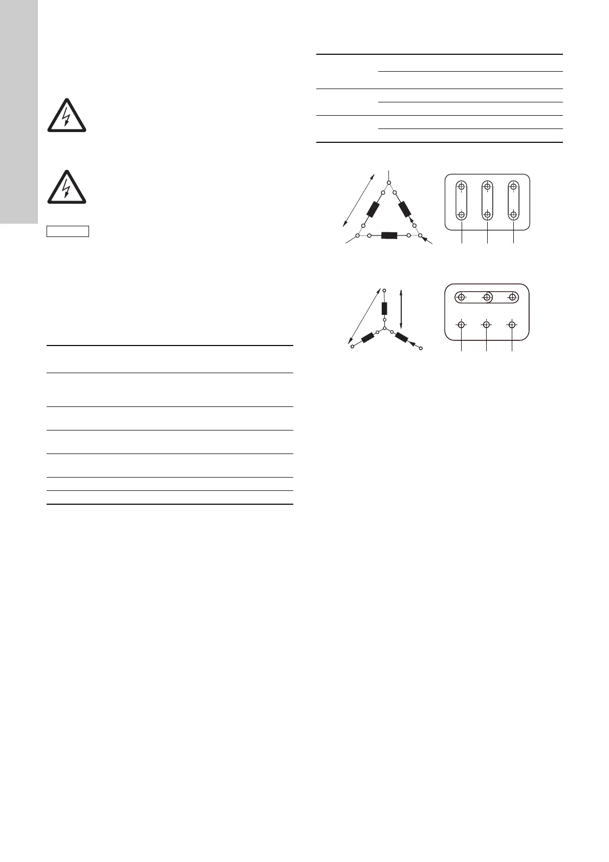
7.2 Three-phase connection
1)
60 Hz motors, 0.37 - 1.1 kW: 220-277/380-440 V.
Fig. 15 Delta connection
Fig. 16 Star connection
If the motor is provided with PTC sensors or PTO contacts, the
connection must be in accordance with the wiring diagram in the
terminal box.
Connect three-phase motors to a motor-protective circuit breaker.
Warning
Connect the CR pump to an external mains switch
placed close to the pump and to a motor-protective
circuit breaker or a CUE frequency converter. Make
sure you can lock the mains switch in OFF position
(isolated). Type and requirements as specified in EN
60204-1, 5.3.2.
Warning
Before removing the terminal box cover and before
removing or dismantling the pump, make sure that
the power supply has been switched off and that it
cannot be accidentally switched on.
Consider whether it is necessary to install an
emergency stop switch.
Motor
[kW]
Number and size
of cable entries
Description
0.25 - 0.55 2 x M20 x 1.5
The holes have precast
threads and are closed with
knock-out cable entries
0.75 - 3.0 2 x M20
The holes are closed with
knock-out cable entries
4.0 - 7.5 4 x M25
The holes are closed with
knock-out cable entries
11-22
2 x M20
4 x M40
The holes are closed with
knock-out cable entries
30-45 2 x M50 x 1.5 Blanking plug
55-75 2 x M63 x 1.5 Blanking plug
Mains supply [V]
Delta connection Star connection
50 Hz
220-240 / 380-415
380-415 / 660-690
60 Hz
220-277 / 380-480
1)
380-480 / 660-690
TM02 6656 1305TM02 6655 1305
W2 U2 V2
U1 V1 W1
U1
U2
V1
V2
W1
W2
L
3
L
2
L
1
W2
U2
V2
U1
U1
V1
V1
W1
U2
V2
W1
W2
L
3
L
2
L
1
 Loading...


