GSK980MDc Milling CNC System User Manual
312
Ⅲ Installation
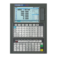
Fig.2-19 Encode signal circuit
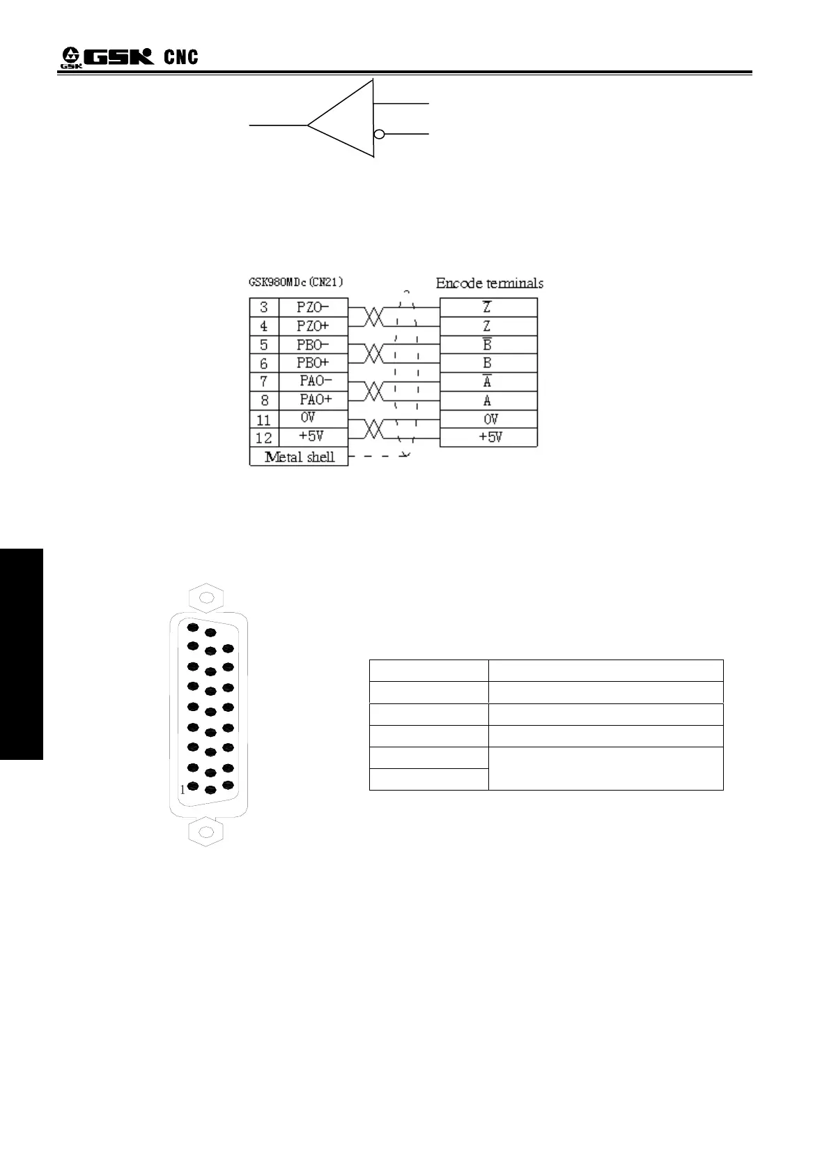
2.4.3 Connection of Spindle Encoder Interface
The connection of GSK980MDc to spindle encoder is shown in Fig. 2-20, twisted pair cables are used
to connection.
Fig.2-20 Connection of GSK980MDc to encoder
2.5 Connection to Handwheel
2.5.1Handwheel Interface Definition
Function of the Ladder Diagram
Address Symbol Function
X6.0 EHDX External MPG X axis selection signal
X6.1 EHDY External MPG Y axis selection signal
X6.2 EHDZ External MPG Z axis selection signal
X6.3 EMP0 External ×1 override
X6.4 EMP1 External ×10 override
X6.5 EMP2 External ×100 override
Signal Explanation
HA+, HA- Handwheel A phase signal
HB+, HB- Handwheel B phase signal
X6.0~X6.5 PLC adress
+24V
VCC, GND
Direct current
PnO
PnO-
AM26LS32
Fig.2-21 CN31 handwheel interface
(DB26 male socket)
13:GND
12:GND
11:GND
10:GND
9:X6.3
8:X6.2
7:
6:X6.1
5:X6.0
4:HB-
3:HB+
2:HA-
1:HA+
26:
25:
24:
23:X6.5
22:X6.4
21:
20:
19:
18:+24V
17:+24V
16:+5V
15:+5V
14:+5V
26
19
10
1