GSK980MDc Milling CNC System User Manual
78
I Programming
Command function
Fine boring cycle is used to bore precise holes. The tool leaves the workpiece when arriving at the hole
bottom, which avoid smooth of workpiece surface influenced by tool trace, and reduces to damage the tool.
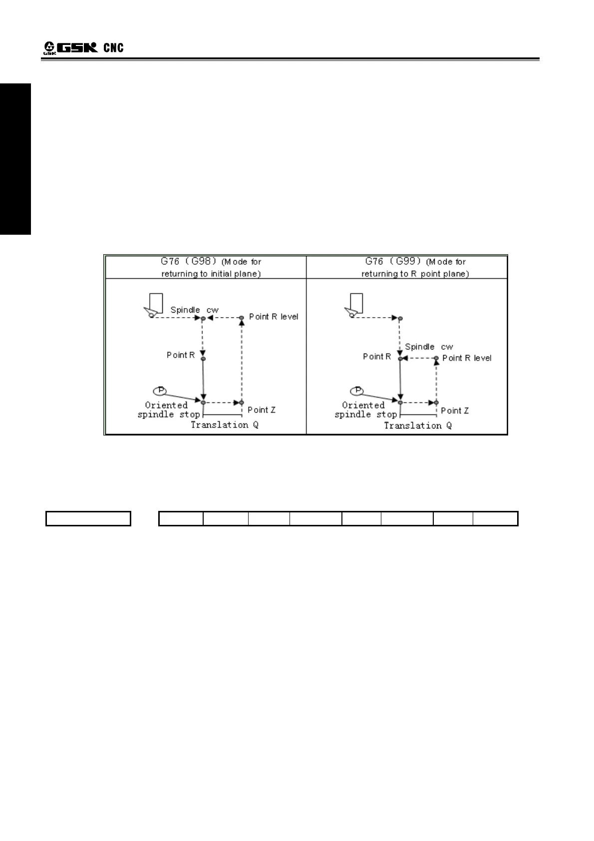
Cycle process
Rapidly traverse to XY plane; ⑴
Rapidly approach point R plane; ⑵
Cut to hole bottom; ⑶
When P is commanded, the system pauses within the time P;⑷
When the spindle orientation is executed, the spindle stops at a fixed position; ⑸
The tool re⑹ versely traverses the distance Q at the hole bottom;
Rapidly return to the initial point plane or point R plane with G98 or G99; ⑺
Offset Q distance to XY initial position;⑻
The spindle rotates clockwise; ⑼
Command path
¾ Related explanations
(1)Q value must be positive, i.e. the negative value is commanded, the sign is invalid; when Q value
is not commanded or Q0 is commanded, Q value is defaulted to 0.1mm; Q value is modal, it can be used
in other fixed cycle commands, and the Q value cannot be big, otherwise, the tool retraction operation
can hit the workpiece, so Q value must be specified to the small.
(2)Offset direction and axis selection are set by No. 584:
0 5 8 4 *** *** *** *** *** *** RD2 RD1
RD1 =1
:
negative tool retraction
;
=0
:
positive tool retraction
RD2 =1
:Y
-axis executing tool retraction
;
=0
:
X-axis executing tool retraction
(
3
)
Direction of tool retraction in final boring cycle is determined by positive/negative X-axis or Y-axis.
(
4
)
M commands selection of spindle orientation is determined by No. 4960, M commands are set to
complete the spindle orientation according to the current ladder.
3.24.2.4 Drilling Cycle, Spot Drilling Cycle G81
Format: G98/G99 G81 X- Y_ R_ Z_ F_ L_ ;
Function: This cycle is used for normal drilling. Cutting feed is performed to the bottom of the hole,
the tool is then retracted from the bottom of the hole in rapid traverse.
Explanation: For the command explanation of canned cycle, see the Table 3-2.
Cycle Process:
(1) Positioning to the XY plane level position at the rapid traverse;
(2) Down to the point R plane at the rapid traverse;
(3) Cutting feed to the bottom of the hole;
(4) Returning to the initial point or point R plane at rapid traverse according to the G98 or G99;
Command Path: