Chapter 3 G Command
67
I Programming
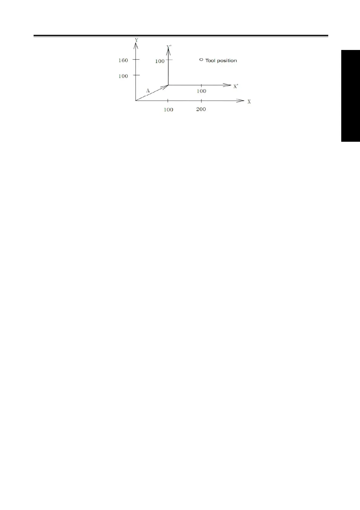
If it performs G92 X100 Y100 commands when the tool is positioned a(t 200,160)in the G54
coordinate system; the offset vector A for workpiece coordinate system 1 is (X’, Y’). And the other workpiece
coordinate systems offset for vector A.
3.22 Additional Workpiece Coordinate System G54.1
The system supports sixes standard workpiece coordinate systems (G54~G59), and also uses 48
additional workpiece coordinates.
Command format:G54.1 Pn or G54 Pn
Pn:specify commands of workpiece coordinate system
n:1~48
Example:
G54.1 P1 additional workpiece system 1┄┄┄┄┄
G54.1 P2 additional workpiece system 2 ┄┄┄┄┄
┇
G54.1 P48 additional workpiece system 48┄┄┄┄
When P command and G54.1(G54) are executed in the same block, a corresponding workpiece
coordinate system in additional workpiece coordinates is selected. The selected workpiece coordinate
system is valid till it is replaced by another one.
When the system is started again, the defaulted workpiece coordinate system is controlled by SCRD of
No.540.
Restrictions:
After G54.1, P must be specified, the workpiece coordinate system 1 (G54.1 P1)is defaulted when P
following G54.1 is not specified in the same block.
P/S alarm occurs when the specified command value in P command exceeds 1~48.
When other G commands containing P command in G54.1(G54) is specified, P command is shared
when they are executed. It is shown below: G54.1 G04 P1000 or G54 M98 P48
Other notes are the same those of G54~G59.
3.23 Coordinate System Rotation G68, G69
The programmed shape can be rotated. By using this function (rotation command), a workpiece can be
rotated with a specific angle. If the pattern of the workpiece comprising some identical shapes, the time
required for programming and the length of the program can be reduced by editing a subprogram and
calling it with the rotation command of the main program. The function is as follows: