GSK980MDc Milling CNC System User Manual
422
Appendix
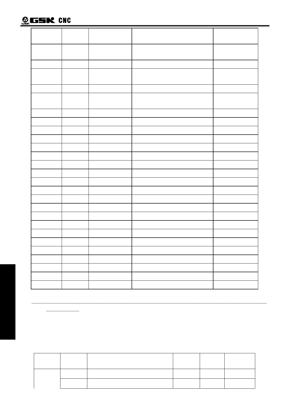
CN15
PLC
Address
Symob Description
Note
5 X5.0
VPO
Spindle speed/position
statement output signal
6 X5.1
SAR Spindle speed arrival signal
8 X5.2
COIN
Spindle orientation
accomplishment signal
4 X5.3
SPAL Spindle alarm input signal fixed address
20 Y5.0
VP
Spindle speed/position switch
signal
21 Y5.1
TAP Rigid tapping signal
22 Y5.2
SRV Spindle CCW
23 Y5.3
SFR Spindle CW
1 CP5+
2 DIR+
3 0V
4 ALM5
7 RDY5
9 GND
10 PC5
11 24V
12 0V
13 SVC
14 CP5-
15 DIR5-
16 0V
17 +24V
18 SET5
s
19 EN5
24 SVC2
25 0V
For detail information about panel keys and panel indicate light address, please see to Chapter 5
Diagnosis of Volume 3.
11.2 Function Configuration
11.2.1 Spindle Rotation Control
z Related signals
Type of
signal
Symbol Significance Pin-out
No
PLC
State
CNC
Diagnosis
Machine panel spindle rotates CCW
X21.7 Input
signal
Machine panel spindle rotates CW
X21.3


 To Next Page