GSK980MDc Milling CNC System User Manual
58
I Programming
z Negative magnification rate
When a negative scale is specified, mirror image is formed (see related explanations of programmable
mirror image)
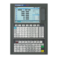
z Scale of different figure
1. Magnification rate of linear scaling
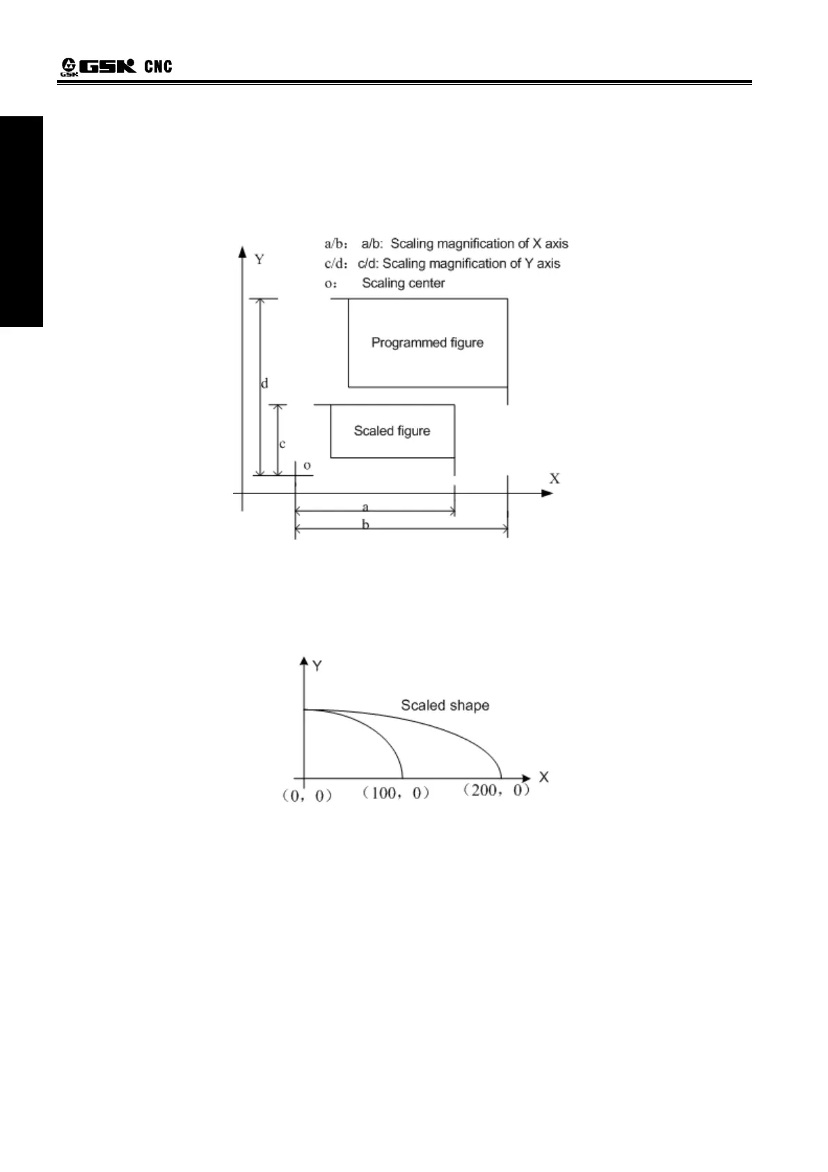
2. Scaling of circular interpolation
Even different magnifications are specified to circular interpolation, tool will not trace ellipse.
When magnifications for axes are different, and the circular interpolation is programmed with radius R,
its figure is as follows, (magnification 2 is applied to X-axis and magnification 1 is applied to Y axis)
G90 G00 X0.0 Y100.0;
G51 X0.0 Y0.0 Z0.0 I2000 J1000;
G02 X100.0 Y0.0 R100.0 F500;
Above commands are equivalent to the following commands
G90 G00 X0.0 Y100.0 Z0.0;
G02 X200.0 Y0.0 R200.0 F500;
Magnification of radius R is depends on I, or J whichever is larger
When different magnifications are applied to axes, and circular interpolation is specified with I, J, K,
alarm occurs after scaled if a circular is not formed.
3. Tool compensation
The scaling is invalid in tool radius compensation values, tool length compensation values and tool
offset values. Only the figure before scaling are proceeded, namely, scaling is done before the calculation of
tool compensation, see the following figure:
 Loading...