Introduction
Service Manual for the Accutherm Ultra Printer 1-7
Mechanism
This section explains the Accutherm Ultra’s theory of operations.
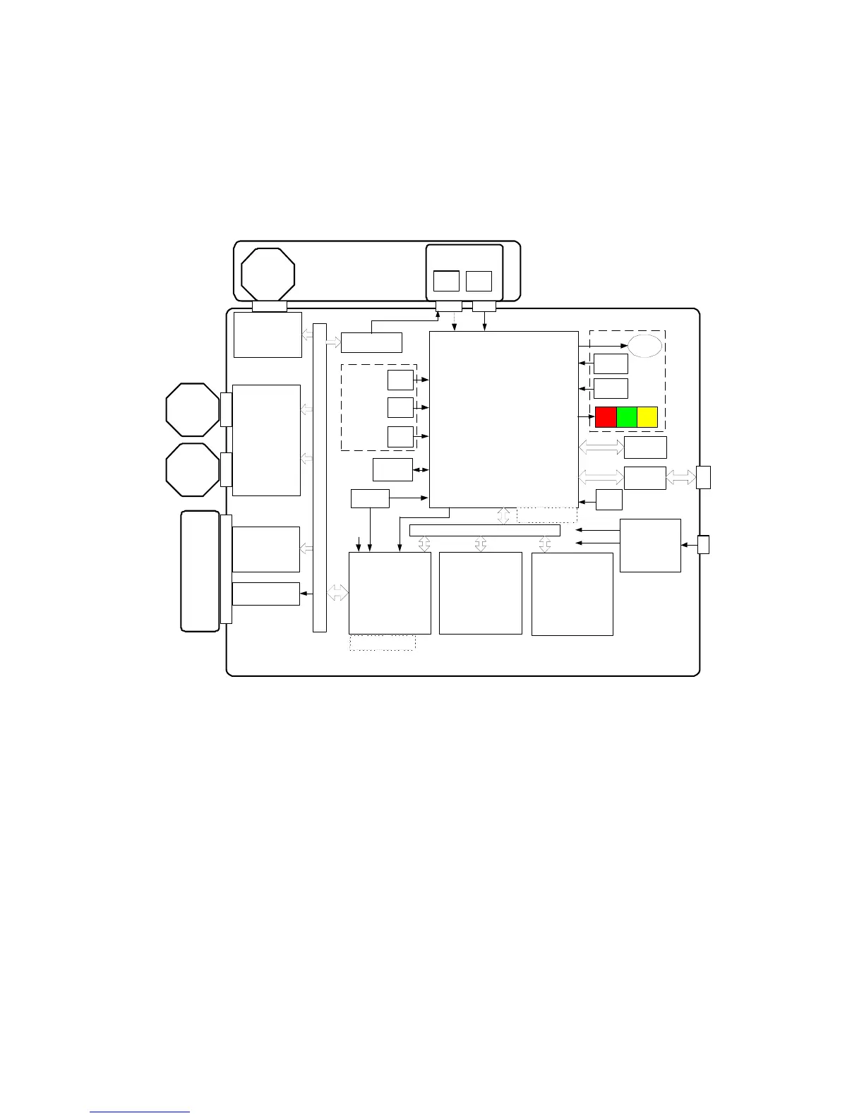
Figure 1-1. Printer Block Diagram
Print Head
The print head in the Accutherm Ultra is a high speed, thick film device
configured as single row of 640 dots spaced at 8 dots/mm for a total printable
width of 80mm (3.15”). Print data is sent from the controller board as a serial data
stream at 8 MHz.The head elements are then activated by signals from the main
controller board to form the image on the paper. The Accutherm Ultra uses a two
level energy control system to compensate for dot history with all timing
controlled by the controller board electronics. The head also contains a thermistor,
which is used to monitor the temperature of the head substrate. Dot energy is
continually adjusted based on head temperature, supply voltage, dot history, and
paper sensitivity. The print head connects to the controller through a 28 position
Flexible Flat Cable (FFC).
Top Cover
Paper Feed
Motor
Dual Step Motor
Driver
Allegro A3988
(1000ma)
Step Motor Driver
Allegro A3983
(400ma)
Knife Motor
Stacker Motor
MCF5353
Processor
(BGA)
RAM
4Mb x 16
(BGA)
FLASH
2Mb x 16
(BGA)
FPGA
(BGA)
Print
Head
Power Supply
and Soft Start
Address/Data Bus
+
Clock
Oscillator
Cover
EEPROM
RS232
Driver
+24 VDC
from
internal
power
brick
+3.3V
+1.5V
Paper
Cut
Home
TOF JAM
On board
sensors
(Interruptive)
Off board sensors
(reflective)
TOF Current
Adjust
F
P
G
A
I
/
O
+
Print Head
Buffer
Print Head
Voltage Control
LED
Te st
Switch
Feed
Switch
On Board
Operator
Interface
LED LED
USB
Protection
Beeper
USB
Clock
Debug Header
Program Header
Not
Populated
+1.5V