GETTING STARTED
15
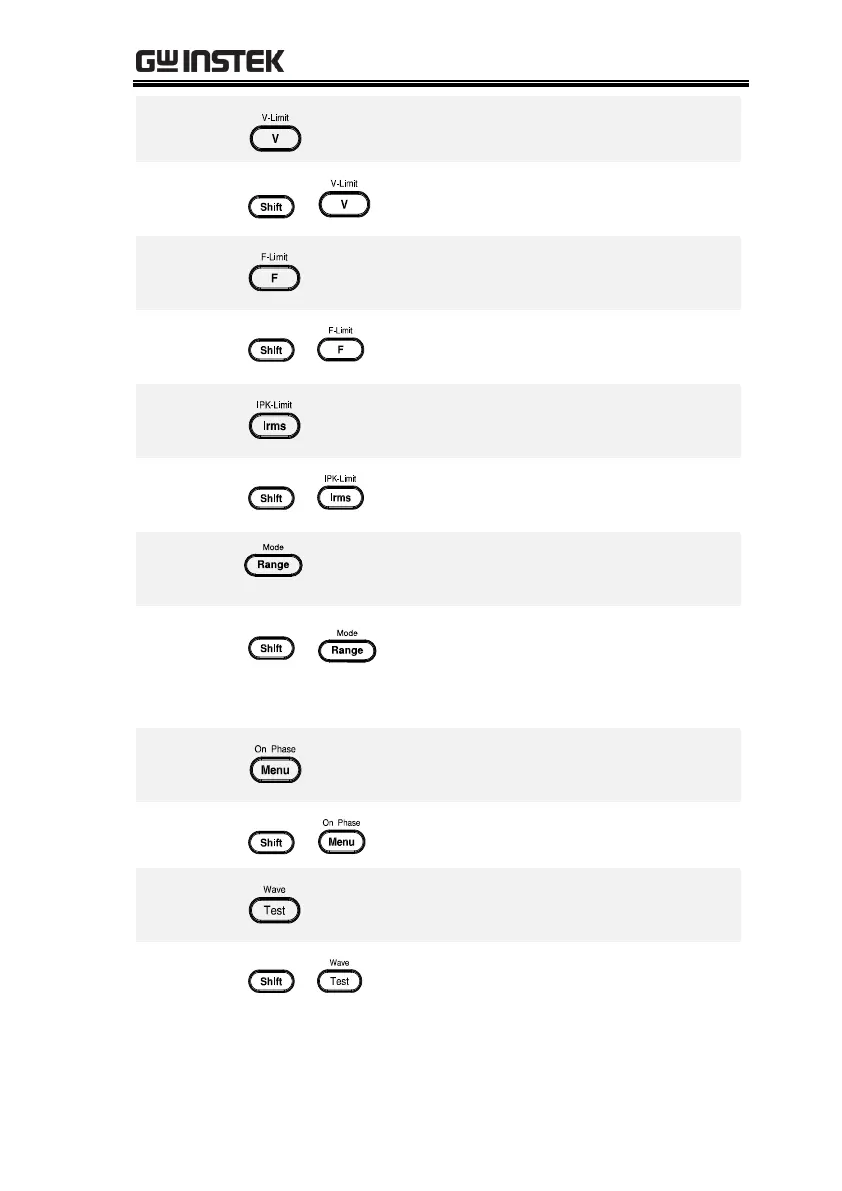
Used for setting the output voltage
Used for setting the output voltage limit
value
Used for setting the output frequency
(DC mode N/A)
Used for setting the output frequency
limit value (DC mode N/A)
Used for setting the maximum output
current
Used to set the peak output current limit
value
Switches between the 100V, 200V and
AUTO ranges
Selects between the AC+DC-INT, AC-INT,
DC-INT, AC+DC-EXT, AC-EXT, AC+DC-
ADD, AC-ADD, AC+DC-Sync and AC-Sync
modes
Enters the Main menu or goes back to
one of the display modes.
Sets the on phase for the output voltage
Puts the instrument into the Sequence
and Simulation control mode.
Selects between the Sine, Square,
Triangle and ARB 1~16 waveforms
(not available for DC-INT, AC+DC-EXT
and AC-EXT)
 Loading...