1-8
Address Description
224.0.0.7 Shared Tree (ST) routers
224.0.0.8 ST hosts
224.0.0.9 Routing Information Protocol version 2 (RIPv2) routers
224.0.0.11 Mobile agents
224.0.0.12 Dynamic Host Configuration Protocol (DHCP) server/relay agent
224.0.0.13 All Protocol Independent Multicast (PIM) routers
224.0.0.14 Resource Reservation Protocol (RSVP) encapsulation
224.0.0.15 All Core-Based Tree (CBT) routers
224.0.0.16 Designated Subnetwork Bandwidth Management (SBM)
224.0.0.17 All SBMs
224.0.0.18 Virtual Router Redundancy Protocol (VRRP)
Ethernet multicast MAC addresses
When a unicast IP packet is transmitted over Ethernet, the destination MAC address is the MAC
address of the receiver. When a multicast packet is transmitted over Ethernet, however, the destination
address is a multicast MAC address because the packet is directed to a group formed by a number of
receivers, rather than to one specific receiver.
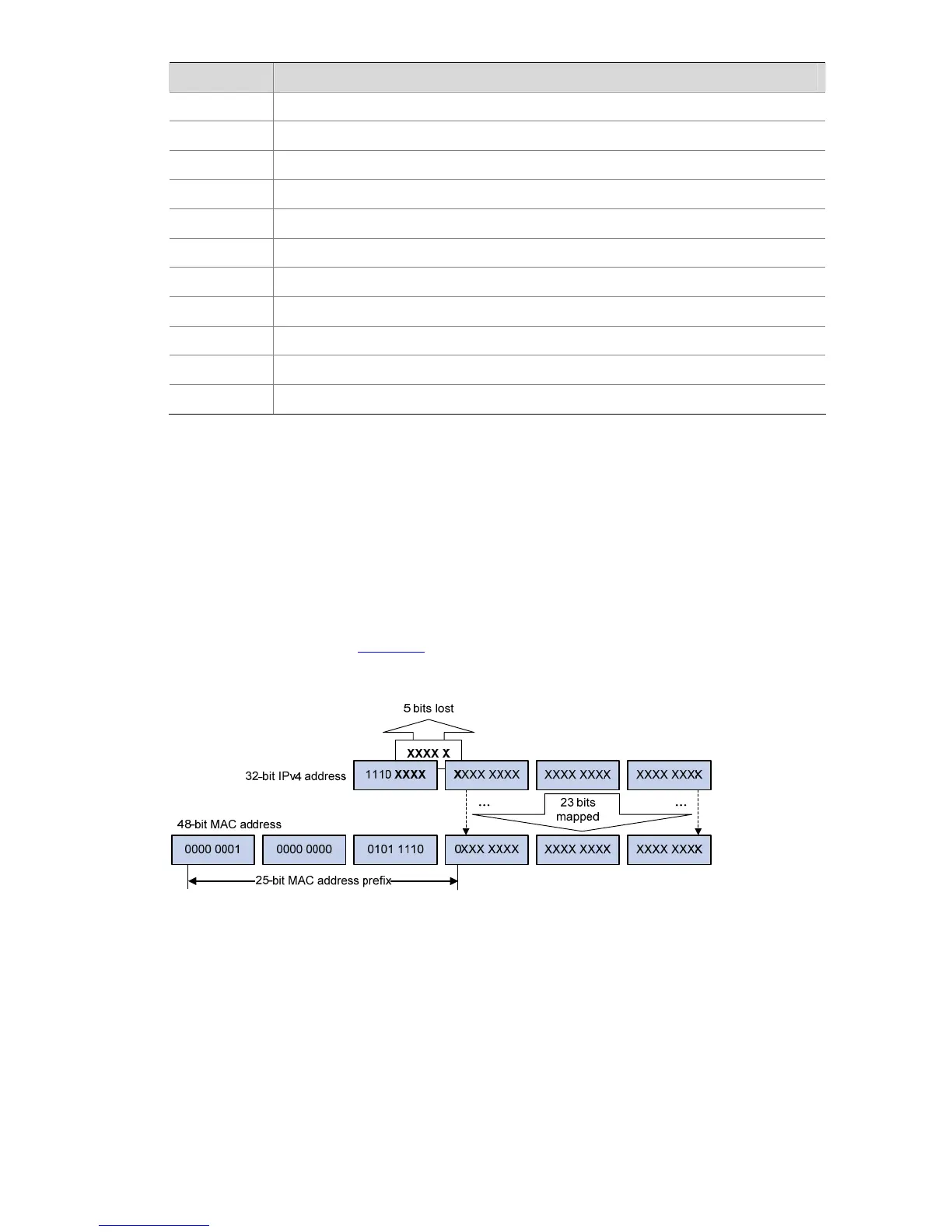
As defined by IANA, the high-order 24 bits of an IPv4 multicast MAC address are 0x01005E, bit 25 is 0,
and the low-order 23 bits are the low-order 23 bits of a multicast IPv4 address. The IPv4-to-MAC
mapping relation is shown in
Figure 1-4.
Figure 1-4 IPv4-to-MAC address mapping
The high-order four bits of a multicast IPv4 address are 1110, indicating that this address is a multicast
address, and only 23 bits of the remaining 28 bits are mapped to a MAC address, so five bits of the
multicast IPv4 address are lost. As a result, 32 multicast IPv4 addresses map to the same MAC address.
Therefore, in Layer 2 multicast forwarding, a device may receive some multicast data addressed for
other IPv4 multicast groups, and such redundant data needs to be filtered by the upper layer.
Multicast Protocols

 Loading...


