28
User Interface
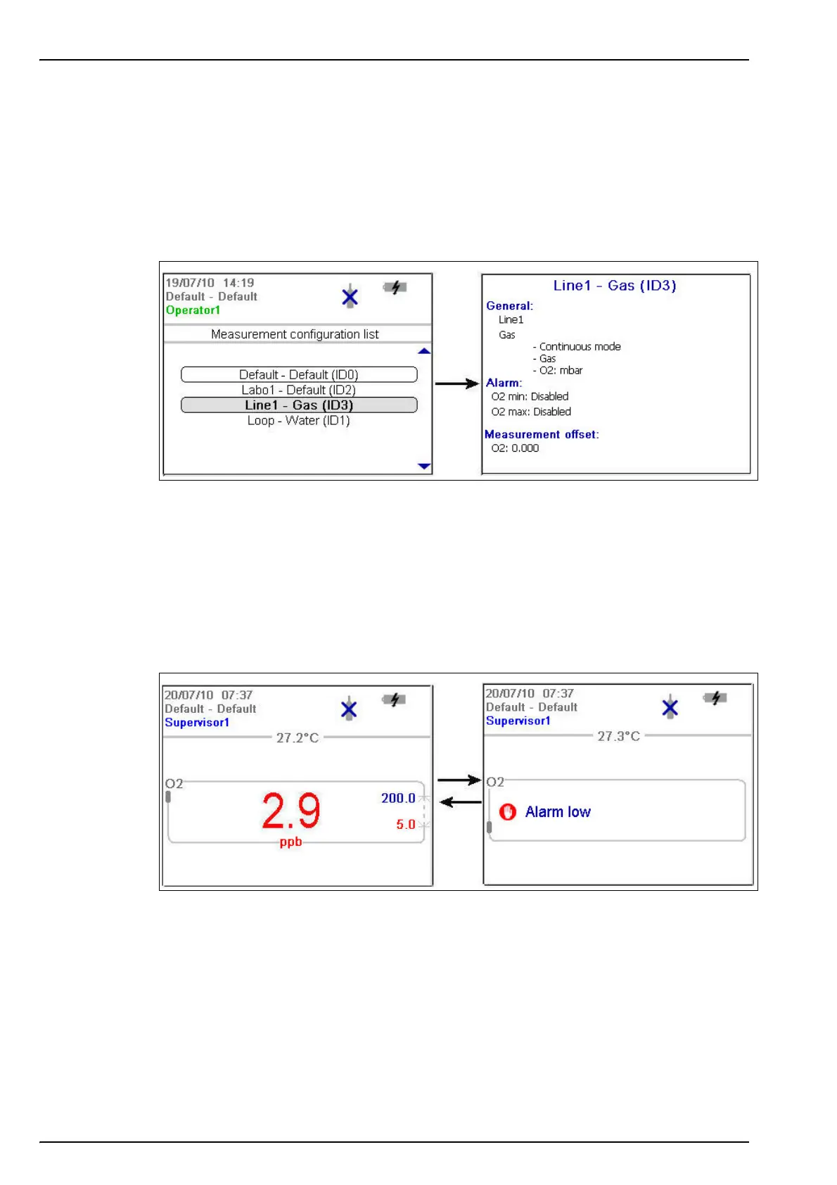
4.4.6 Measurement configuration list
From the measurement screen, press the right arrow key until the list of measurement
configurations stored in the instrument (below left) is displayed.
Note: These configurations are defined by the user on the PC (see Create new measurement configuration
table on page 20) and imported into the instrument (see Transfer files to the instrument on page 21). Only
the default configuration (ID0) can be edited by the user from the instrument. To do this the user must be
logged on at supervisor level and the default parameters can then be edited from the Main Menu as
described in Default measurement configuration settings on page 34.
Press the up and down arrow keys to scroll through the list of measurement configurations.
When the required one is highlighted press the Enter key to select it. The selected configuration
details will be displayed on screen (above right).
Press the Enter key again to select this configuration and return to the measurement screen, or
Cancel to reject it and return to the measurement configuration list screen.
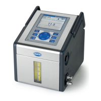
4.4.7 Measurement alarms
If a problem occurs during measurement, the system will alternate every second between the
measurement screen (shown left below) and the error message screen (shown right below).
In the example illustrated above, the measurement value is displayed in red to indicate a
measurement outside the pre-defined alarm limits. The alarm low value on the right side of that
screen is also displayed in red to indicate the reason the measurement value is in error.
The error message screen gives the reason why the measurement is invalid (i.e. Alarm low in
the example above).
Note: If the measured value goes back above this low value, the value is again displayed in blue and the
error message screen is no longer shown.