14
Installation
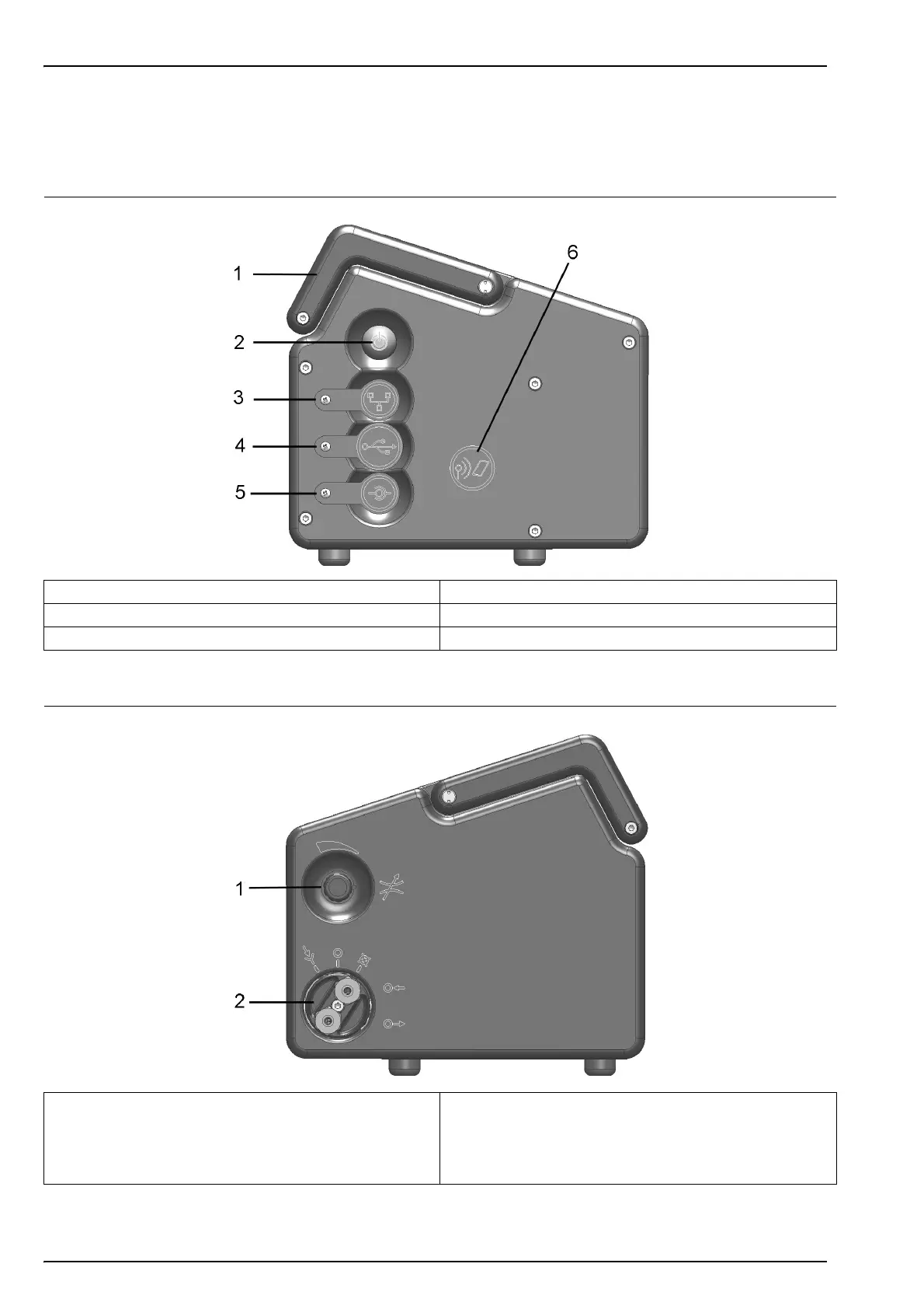
3.6 Instrument switches and connectors
The following diagrams illustrate the side views of the instrument and their key features:
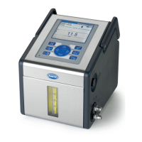
Figure 4 Left side view
1 Handle 4 USB connection
2 Instrument ON/OFF switch 5 External power supply connection
3 RS232 connection 6 Card identification system (option not yet available)
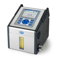
Figure 5 Right side view
1 Sample flow adjustment valve 2 Sample flow valve with inlet and outlet connections (the
sample inlet is at the top of the valve and the outlet at the
bottom). The valve has three positions: Sample line
PURGE; Sample flow ON; Sample flow OFF