40
Maintenance and Troubleshooting
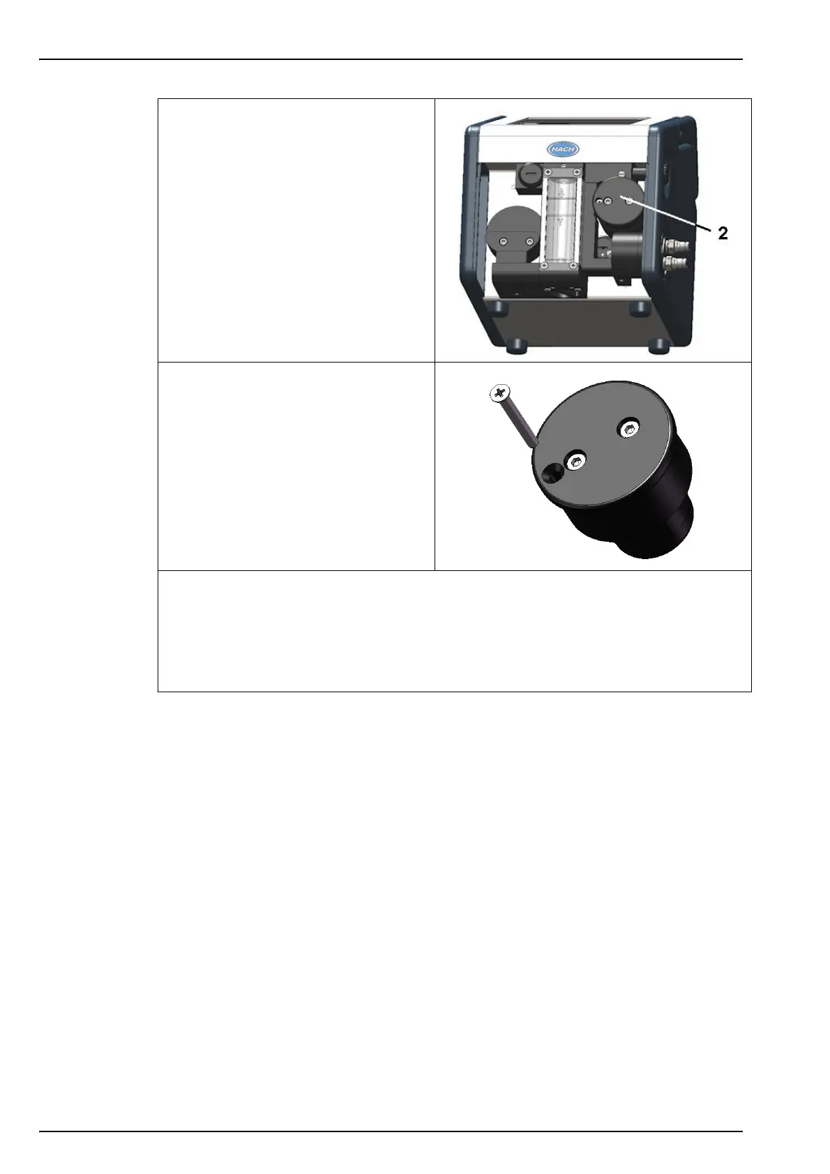
2. Once removed, the flow chamber
assembly (No. 2) can be seen located
to the right of the flow meter.
3. Remove the holding screw from the
flow chamber assembly.
4. Holding the assembly between thumb
and forefinger, gently ease it out of the
instrument and discard.
5. Replace the assembly with the new one from the maintenance kit, Put the new assembly
back in place in the instrument and secure with the holding screw. A guide rod is in place
to ensure correct positioning.
6. Replace the front guard and secure in place with the 2 screws underneath the instrument.
7. After changing the spot, a sensor calibration must be performed before using the
instrument for measurement purposes (see Calibration on page 33 for details).