Do you have a question about the hager hw+ and is the answer not in the manual?
Provides essential safety advice for proper usage and to prevent property damage.
Defines the necessary qualifications for operating and maintaining the equipment.
Outlines the intended applications and proper handling of Hager products.
Explains the manual's structure, purpose, revisions, and contact information.
Lists the different versions and their publication dates for the documentation.
Lists related publications and technical information available for reference.
Provides Hager Electro's address, phone number, and website for inquiries.
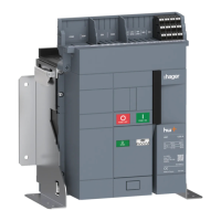
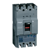
Provides an overview of the sentinel Energy trip unit's functions and versions.
Details the communication interfaces and methods for the hw+ system.
Specifies the minimum and recommended system requirements for the software.
Specifies the supported operating systems (iOS and Android) for the mobile application.
Describes Modbus RTU and TCP modules for unit communication.
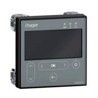
Details features, functionalities, and specifications of the HTD210H panel display.
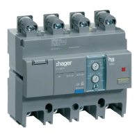
Explains the role of the HWY210H adapter for panel display connection.
Details the need for adequate dimensioning of the external supply for accessories.
Explains the user interface, navigation buttons, and display panel of the trip unit.
Details how to navigate the menu structure using the tree interface and available actions.
Guides the user through the initial setup process for display language and Live mode.
Explains how Live mode displays measurements or protection settings and allows view adjustments.
Details the step-by-step process for adjusting protection parameters via the trip unit interface.
Lists parameters within the PROTECTION menu, including Long Time, Short Time, Instantaneous, Earth, and Neutral protections.
Provides configuration details for various advanced protection functions like voltage, frequency, and unbalance.
Explains how to switch between numerical and graphical display modes for measurement screens.
Details configuration for prealarms and custom alarms, including thresholds and conditions.
Covers settings for language, display, network, communication, reset, and other configurations.
Displays status, history, communication status, and identification information of the trip unit.
Accesses mode settings like protection profile (A/B) and trip command.
Details the long time delay protection against overcurrent, including its system, IEC/ANSI correspondence, and setting adjustment.
Details the IEC 60255-151 standard for long time delay protection and its tripping time calculation.
Details the short time delay protection against low current short circuits and its parameters.
Details the time-independent instantaneous protection against high short circuit currents.
Details the earth fault protection used against phase-to-earth faults.
Details neutral protection, its curves, threshold adjustments, and time delay.
Explains the ZSI function for limiting electro-dynamic constraints and improving selectivity.
Explains dual settings (A+B) for different sources and parameters, and how to activate them.
Lists seven optional advanced protection functions available for installation monitoring.
Details the undervoltage protection (UV-27), its operating principle, and adjustment parameters.
Details the overvoltage protection (OV-59), its operating principle, and adjustment parameters.
Details the underfrequency protection (UF-81L), its operating principle, and adjustment parameters.
Details the overfrequency protection (OF-81H), its operating principle, and adjustment parameters.
Details the reverse active power protection (RP-32R) for detecting synchronous motor function.
Details the current unbalance protection (UNBC-46) for monitoring phase current unbalances.
Details the voltage unbalance protection (UNBV-47) for monitoring phase voltage unbalances.
Provides a summary of measurable values (voltages, currents, power, energy) available on different displays.
Lists basic electrical values measured in real-time by the trip unit.
Explains how the trip unit calculates real-time maximum and minimum values since the last reset.
Explains how current and voltage unbalances are calculated and expressed as percentages.
Details the calculation of active, reactive, and apparent power per phase and total.
Details total, partial, and multi-tariff energy measurements (active, reactive, apparent).
Explains how the trip unit calculates average current and power values over specified time intervals.
Explains how the trip unit calculates current (THDi) and voltage (THDU, THDV) harmonic distortion.
Explains the calculation of power factors and cos φ, and their benefits.
Explains how the trip unit monitors voltage and current harmonics up to the 40th order.
Classifies PMD devices according to IEC 61557-12 and details measurement precision and conditions.
Explains how to configure electrical network parameters like voltage, power, frequency, and power sign convention.
Covers configuration of ENVA, ENCT, phase sequence, calculation conventions, and interval settings.
Describes the 9 types of alarms and their colour-coded severity display on the sentinel Energy unit.
Explains PTA overload prealarms for warning about impending overload situations.
Alerts about imminent tripping due to current overload, activating at ≥ 105% of Ir.
Displays trip alarms with message windows indicating trip type and cause, requiring acknowledgment.
Allows monitoring of measuring events via custom alarms defined by parameters.
Details how advanced protection alarms are displayed as message pop-ups on the sentinel Energy display.
Alerts about brief variations in network voltage (falls or increases) as per IEC 61000-4-30.
Alerts about malfunctions in the trip unit, categorized as critical or non-critical.
Addresses maintenance and backup battery alarms, including indicators and actions.
Explains programming the OAC output contacts module for signaling events locally.
Explains the remote reset function for alarms and output contacts via digital input.
Explains how to switch between multi-tariff energy meters via digital input or Modbus communication.
Details how to momentarily deactivate advanced protections using digital input, display, or software.
Explains how to switch between protection profiles A and B locally or remotely.
Allows electromechanical tripping tests in two modes: full chain or electronic part only.
Explains how to establish a Bluetooth Low Energy connection and manage its activation and auto-disconnection.
Explains Modbus RTU and TCP communication functions, modules, and configuration.
Details event categorization, memory, types, unlocking, and severity levels.
Compiles lists of events from Trip, Alarm, System, Error, Diagnostic, Operation, Protection, Measurement, and Test sections.
Illustrates display examples for trip, advanced protection, system, custom, and other alarms.
Explains the meaning of the maintenance indicator and the required actions.
Provides step-by-step instructions for replacing the backup battery, including initial, intermediate, and final steps.
Lists references for standard, meter plus, harmonic, advanced, and ultimate rating plugs by current rating.
Provides step-by-step instructions for replacing the rating plug, covering all stages from preparation to completion.
Details steps for fixing screws, connecting breaker, replacing cover, and checking settings.
Defines terms from ANSI to PF, including protection types and protocols.
Defines terms from Breaking Capacity to ZSI, including technical concepts and abbreviations.
Provides MIT license text and conditions for the LVGL software.
Provides MIT license text and conditions for the FreeRTOS kernel software.
| Voltage Rating | 230/400V AC |
|---|---|
| Standards | IEC 60898-1 |
| Mounting | DIN Rail |
| Rated Current | 6A |
| Number of Poles | 1P, 2P, 3P, 4P |
| Tripping Characteristic | C |