504
Wired controller is available
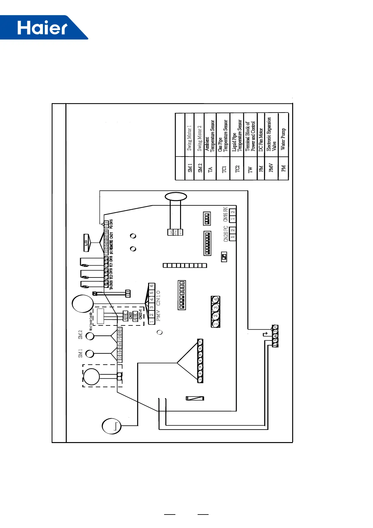
Symbol
Description
TA
TC1
TC2
FM
PMV
Ambient
T
emperature Sensor
Gas Pipe
Temperature Sensor
Liquid Pipe
T
emperature Sensor
Terminal Block of
P
ower and Control
DC Fan Motor
Electronic Expansion
V
alve
SM 1
SM 2
Swing Motor 1
Swing Motor 2
8
7
6
5
4
1
2
3
1
2
3
2
1
3
2
1
1
2
1
2
10
9
8
7
6 5 4 3
2
1
CN16 RK
SW
FLASH
TA CN20
TC2
CN19
IR
REMOTE
CN21
PQ
CN15
TC1
CN18
1
2
Emergency CN31
1
2
3 4 5 6
PMV CN10
L
CON1
N
CON2
1
2
CN26 PC
1
2
3
4
5 6
7
CN4 DC FAN
Vsp
FG
15V
GND
310V
4 3
2
1
CN34
NET
FUSE
250
VAC/T3.15A
LED3 LED4
LED5
FLZ/PUMP
CN7
1
2
Motor
PMV
SW03
SW08
ON
1
2
3 4
5
6
7 8
ON
1
2
SW01
ON
1
2
3
4
5
6
7
8
L
3
4
N
TW
Transmission Wiring
(To O.D unit)
To Power
Supply
LCD
FM
SW02
ON
1
2
3 4
1
2
3
FS CN13
step motor
CN9
1
2
3
5
6
7
8
9
10
4
SM 1
SM 2
M
M
A
B
C
CN22 -1
Wired Remote Controller
A
B
C
CN22
PM
FS
PM
Water Pump
1.Wired controller connects to CN22 on PCB.
2.Under group control with one wired controller,
the wired controller connects to CN22 on PCB
of master unit, then connects all of CN22-1 ports
from master PCB to all slave PCB in serial.In this
group, the max qty of indoor units is 16.
3.If two wired controllers control one indoor unit,
master controller connects to CN22 while slave
controller connects to CN22-1.
TW
AS182/242MGERA PCB code: 0151800141A