511
High Wall Type
Indoor Unit
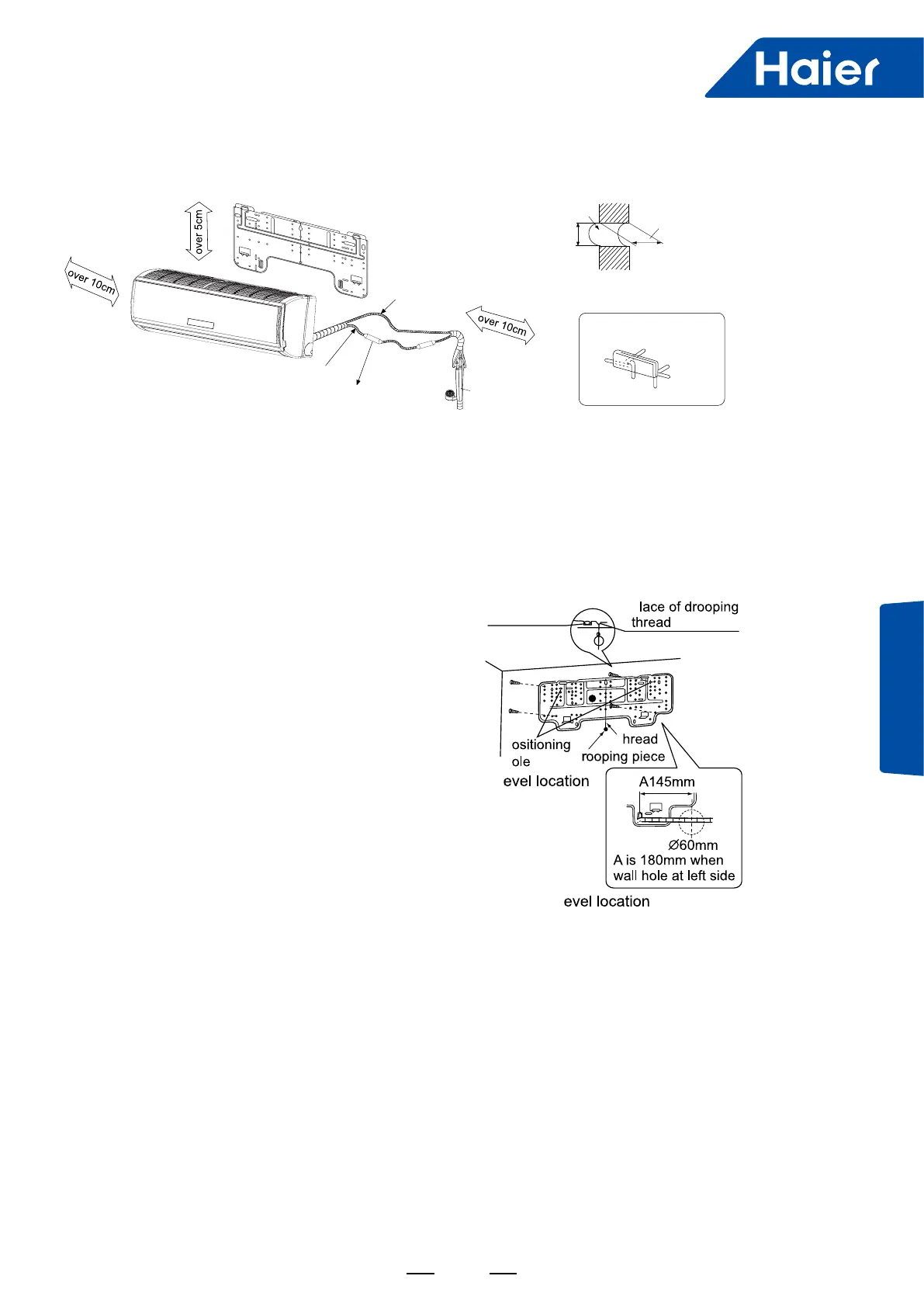
3. Installation Drawing of Indoor Units:
(1) Positioning Wall Pad & Locating Wall Holes
Fix the pad according to the installation location and the pipe layout of indoor unit (please refer to the installation
drawing).
Installation should be done under the crossbeam or on the at wall near the pillar. First x the pad with a steel nail
on the wall.
Drop a thread with a bolt through the pad center or use a level meter to nd the level.
Then x it with a concrete steel nail, (if it is xed by the expansion bolts, drill holes on the wall according to the pad
position with the electric drill ).
(bore: 4.8mm, put the plastic sleeves into the holes,
stick the panel onto the wall, and then position the
pad with 4×25 bolts) and measure the position of
the wall hole A.
(2) Drilling Hole & Mounting Guard Ring
Drill a hole of 60mm bore with a slight tilt downwards to the outside, mount the guard ring, and seal it with gesso or
putty after nishing the installation.
(3) Arranging Wiring of Indoor Unit
Arrange the layout of connection pipe, drain pipe, connecting line, signal line and air refreshing pipe according
to the locations of your indoor unit, outdoor unit and wall holes, with drainage hose lower, connecting line upper.
Intercrossing winding is not allowed between the mains line and the connecting line, and the drain pipe (especially
in the indoor unit and the inside of machine) should be winded with heat insulating materials for heat preservation.
Wall pad
Gas pipe
Liquid pipe
Filter
Tape
Heat insulating
material
Side of indoor Side of outdoor
Thickness
of wall
Cross section of wall hole
Ø
60mm
Wall hole
Layout of pipes
Right rear
Left
Left rear
Right
Downwards
Lashing wire
P
T
P
D
H
L
L
Wall pad