546
T
C
P
W
Cutting and Enlarging
Connecting
Vacuumizing
Open All Valves
Checkup for Air Leakage
1. Installation
Cutting or enlarging pipes should be proceeded by
installation personnel according to the operating
criterion if the tube is too long or are opening is
broken.
1. Connecting circular terminals:
The connecting method of circular terminal is
shown in the Fig. Take off the screw, connect it to
the terminal tier after heading it through the ring at
the end of the lead and then tighten it.
2. Connecting straight terminals:
The connection methods for the circular terminals
are shown as follows: loosen the screw before
putting the line terminal into the terminal tier,
tighten the screw and conrm it has been clamped
by pulling the line gently.
3. Pressing connecting line
After connecting line is completed, press the
connecting line with clips which should press on
the protective sleeve of the connecting line.
Vacuumize from the stop valve of outdoor units
with vacuum pump. Refrigerant sealed in indoor
machine is not allowed to use for vacuumization.
Open all the valves of outdoor units. [NB: oil
balancing stop valve must be shut up completely
when connected one main unit.]
Check if there is any leakage at the connecting part
and bonnet with hydrophone or soapsuds.
A
A
2. Dismantling
During the installation of this series machines, fasten
the wall pad on the wall rst, hang the machine on the
pothook, push it towards the wall pad until the sound
of 'pa' 'pa' is heard. At this time, the agraffes of the
indoor unit have hitched on the pad, as shown in the
Fig.1 with dotted line.
During dismantling this series machines, push
agraffes at the bottom of indoor unit upwards to
release them, as shown in Fig.3, and pull up the
bottom of indoor unit outwards gently and then raise
the unit upwards in the bevel direction to release the
pothook at the upper part of the wall pad, as shown in
Fig.3.
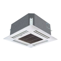
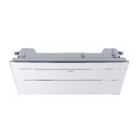
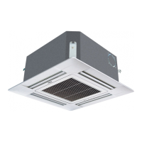
Installing and Dismantling Indoor Unit