569
HRV
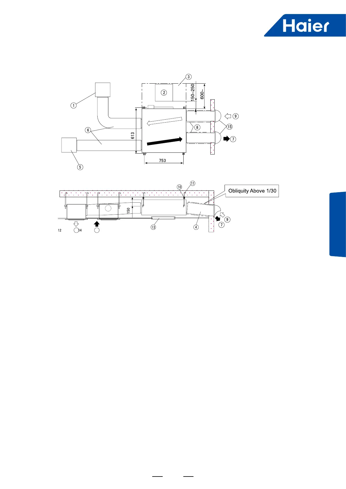
Installation Diagram
1. Outlet Grille—Available on the Site
2. Service Lid (dia.450mm)
3. Service Space for Maintaining Heat
Exchange Device, Air Screen, Control Box
and Fan.
4. Air Hose (available on the site)
5. Inlet Grille (available on the site)
6. Air Hose or Bourdon Tube (available on the
site)
7. EA (exhaust air)
8. Heat Insulant—available on the site
9. OA (outdoor air: fresh outdoor air)
10. Suspending Rack to Reduce Vibration (available on the
site)
11. Suspending Bolt (available on the site)
12. SA (sending air)
13. Service Lid (dia.450mm) (available on the site)
14. RA (return air)
15. Dome Shield (available on the site)
<Air Hose Installation Tips>
■ Silencing box and soft hose are recommended when installing the unit in noise sensitive places.
■ Airow volume and noise shall be considered for special places when choosing installing material.
■ When outdoor air enters ceiling, the ceiling air temperature shall rise. Therefore, heat insulation shall be handled
with the metal parts in the ceiling.