73
Subject to change without notice
MANUAL ADJUSTMENT PROCEDURE HM1508-2
– Press “PROBE ADJ.” pushbutton, “COMP. TESTER On” function key and press AUTO/CURSOR-MEASURE
and SETTINGS pushbutton simultaneously to enter the “Settings Adjust” menu.
– Press “Adjust 1” function key.
– Press “RO Adjust” function key to enter the “Adjust 1 RO Adjust” submenu.
– Press “Trace Rot.” function key.
– Turn INTENS knob to adjust the Service Rectangle exactly parallel to the horizontal lines of the graticule.
– Press function keys to call “Y Position”, “Y Mag.”, “X Position” and “X Mag.” to adjust the Service Rectangle
until it is adapted to the graticule lines.
– Turn INTENS knob in combination with Y and/or X Mag function, to adjust the rectangle for 6 division height
and 8 division width.
– Turn INTENS knob in combination with Y and/or X Position function, so that the cross symbol in the center of
the Service Rectangle is congruent with the graticule center.
– Press “Save” function key to store the settings into user memory.
– Press REM pushbutton (EXIT MENU) to return to the Adjust Adjust 1 menu and continue with item 25.
– Check that Adjust Adjust 1 menu is present.
– Press “YP” function key to call the “Adjust 1 YP”
submenu.
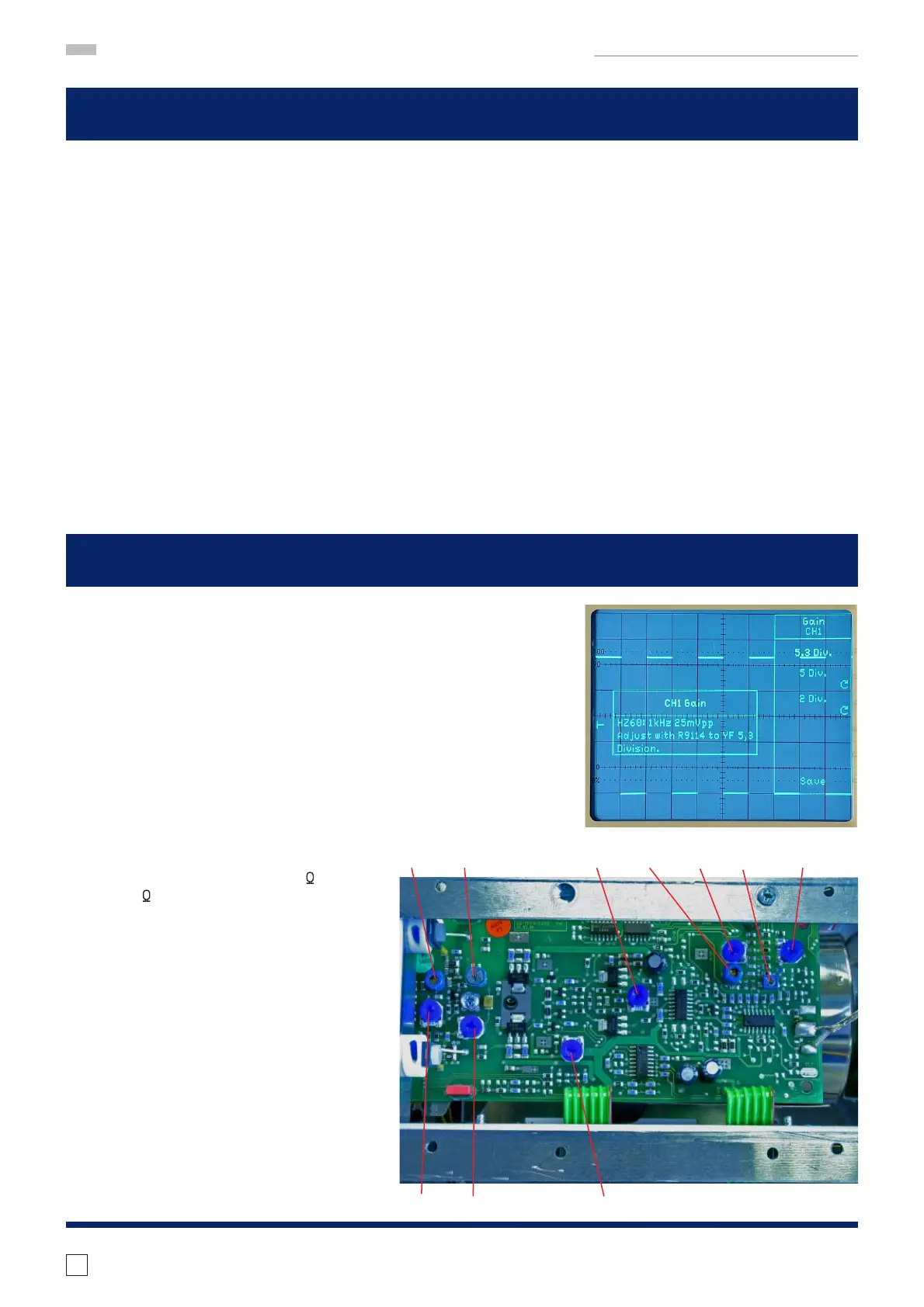
– Press “Gain” function key to call “YP Gain”
menu.
– Press “CH 1” function key.
– Press “5.3 Div.” function key.
– Connect a 25 mV
pp
(accuracy ± 0.1%), 1
kHz square wave signal via 50
cable
and 50 through terminator to input CH
1.
– Locate and identify R9114 on YF-Board.
– Adjust R9114 for 5.3 div signal height.
– Continue with item 26.
R9114
25 YP CH 1 Analog Gain
24 Readout Adjustment (Software Adjustment)
C9001 C9037 R9114 C9045 R9118 C9009 R9149
R9034 R9126 R9057
correct

 Loading...


