90
Subject to change without notice
MANUAL ADJUSTMENT PROCEDURE HM1508-2
C4809, C4810
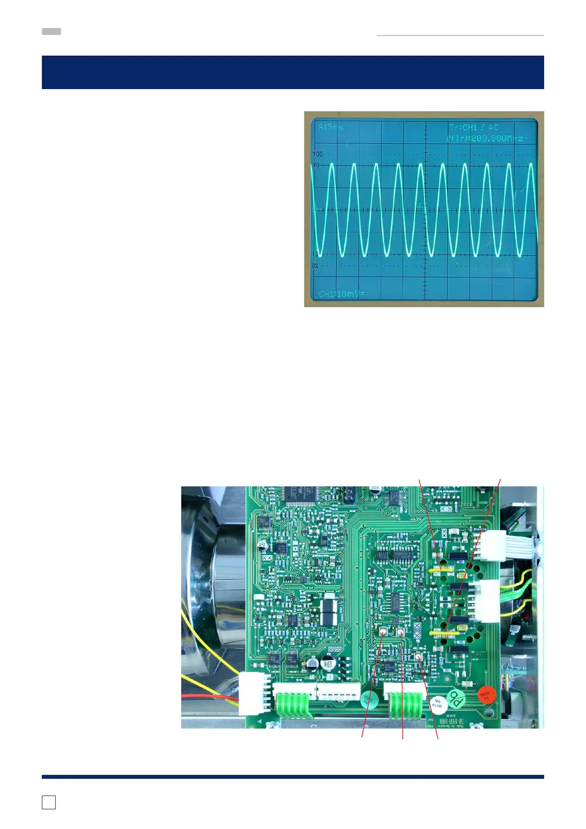
64 X-Mag. x10 Trace Start Linearity
– Locate and identify C4809, C4810 (2 wires close
to the X fi nal amplifi er transistors) on MB-Board.
– Set TIME/DIV knob for “TB: 50ns” display.
– Press MAG x10 pushbutton so that x10 is lit.
– Connect a 200 MHz sine wave signal (accuracy
0.1 ppm or better) to the input of CH 1.
– Turn CH 1 VOLTS/DIV knob for a suitable signal
height of 5 divisions.
– Set POSITION 1 knob on the front panel for a
reading at the horizontal center line of the grati-
cule.
– Set LEVEL A/B knob on the front panel for stable
triggering.
Adjustment Procedure:
– Move trace with HORIZONTAL knob (front panel)
so that the fi rst zero crossing coincides with the
fi rst or second vertical graticule line at the left
side of the screen.
– Adjust (move) C4809 and C4810 so that 1 signal
period per division is displayed and the rightmost
zero crossing coincides with the vertical graticu-
le line as on the left side.
C4810 C4809
R4086 R4840 R5107
correct

 Loading...


