Basic Operation
DSO8000E Series HandHeld Oscilloscope User Manual 34
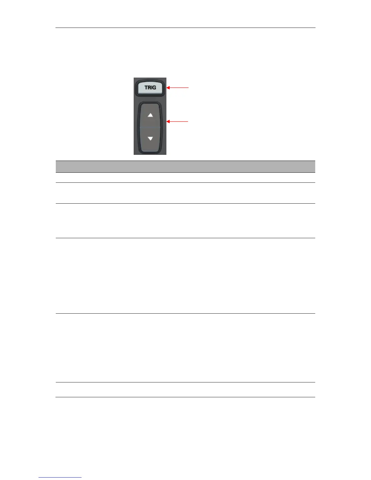
TRIG Level
It sets the amplitude level the signal must cross to cause an acquisition when using the Edge or
Pulse Width trigger.
By default the oscilloscope uses the edge trigger which
triggers the oscilloscope on the rising or falling edge of the
input signal when it crosses the trigger level (threshold).
Select the input source as the trigger signal.
CH1, CH2: No matter the waveform is displayed or not, a
certain channel will be triggered.
EXT/5: Same as EXT option, but attenuates the signal by
a factor of 5 and allows a trigger level range of +6V to -6V.
Select a trigger mode.
By default, the oscilloscope uses the Auto mode. In this
mode, the oscilloscope is forced to trigger when it does
not detect a trigger within a certain amount of time based
on the TIME/DIV setting. The oscilloscope goes into the
scan mode at 80ms/div or slower time base settings.
In the Normal mode, the oscilloscope updates the display
only when it detects a valid trigger condition. New
waveforms are not displayed until they replace old ones.
Use this mode to just view valid triggered waveforms.
Only after the first trigger does the display appear.
AC
DC
Noise Reject
HF Reject
LF Reject
Select the components of the trigger signal applied to the
trigger circuitry.
AC: Blocks DC components and attenuates signals below
10Hz.
DC: Passes all components of the signal.
Noise Reject: Attenuates the noise conponents.
HF Reject: Attenuates the high-frequency components
above 80kHz.
LF Reject: Blocks DC components and attenuates the
low-frequency components below 8kHz.
Set the vertical trigger postion to the channel zero level
postion.
NOTE: Trigger coupling only affects the signal passed through the trigger system. It does
not affect the bandwidth or coupling of the signal displayed on the screen.
Video Trigger
 Loading...