6 - Maintenance
196
TWIN System, Priming of Blower Transmission
If the hydraulic blower transmission has been dismantled, or the pump or the motor has been changed, the following
priming procedure must be carried out before starting up the transmission:
1. Fill the oil tank with fresh, clean oil to the top of the sight glass.
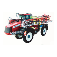
2. Fill the pump housing with oil through the drain pipe (D) which is
dismantled at the tank connection. Reconnect and tighten.
3. Ensure that the oil level in the gear box is sufficient.
4. Remove the drain hose (D) from the motor outside the blower
housing.
5. In the tractor cabin, set the blower speed at 0 rpm.
Engage the tractor’s PTO with the engine running idle - and wait a few minutes.
6. Set the blower speed at 200 rpm.
7. After a while the oil will start dripping constantly. Refit the drain hose and tighten.
8. With the tractor’s PTO set at 540/1000 rpm depending on your pump model, the blower should now rotate at
maximum speed (3100 rpm).
9. Check the oil level at the sight glass for the hydraulic tank on the sprayer.
10. Check the pressure gauge for the suction filter (indicator is in the green area).
11. Retighten hose connections and check for leaks.
12. Check the blower speed and feed pressure - see below.
Pressure Adjustment of Blower Transmission
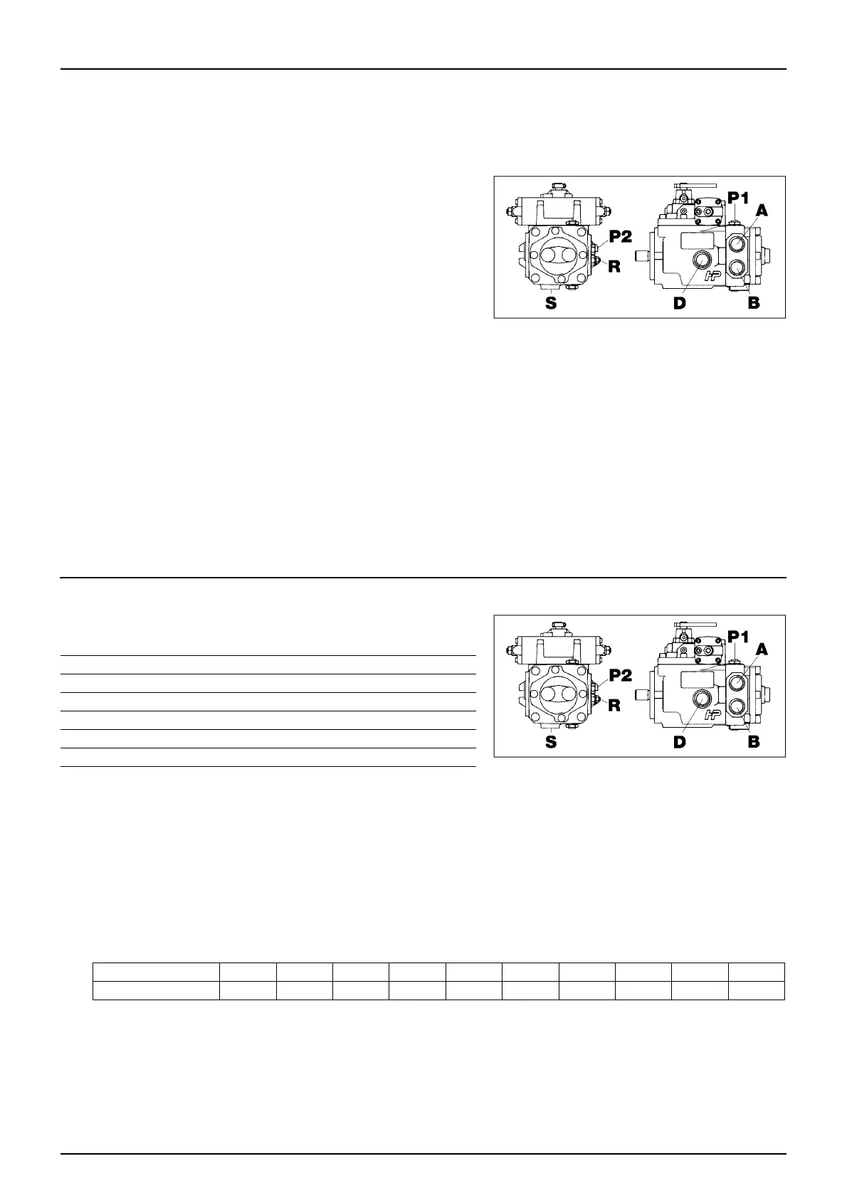
Ports and connectors for blower transmission:
The transmission feed and working pressure are checked as follows:
1. P1 connector - working pressure: Connect a pressure gauge (0 - 400 bar).
P2 connector - feed pressure: Connect a pressure gauge (0 - 40 bar).
2. Set the tractor’s PTO at 540/1000 rpm depending on your pump model.
3. Set the blower at maximum speed (3100 rpm).
4. Check the feed and working pressure:
Feed pressure P2: 15-20 bar
5. Adjust feed pressure (R) if needed.
μ
ATTENTION! Failure to reach the feed and working pressure indicates that the transmission needs overhauling.
A=Pressure port
B=Return port
D=Drain port
P1 = Connector for measurement of working pressure
P2 = Connector for feed pressure
R = Adjustment screw for feed pressure
S=Suction port
Boom width 18 m 20 m 21 m 24 m 27 m 28 m 30 m 32 m 33 m 36 m
Working pressure P1 180 bar 190 bar 200 bar 240 bar 240 bar 240 bar 240 bar 240 bar 240 bar 240 bar