4 - Sprayer Setup
90
Speed Sensor for Sprayer
The speed sensor and speed ring are located at the inside of the
sprayer’s right wheel. The sensor is an inductive type that requires a
metallic protrusion like the speed ring to pass by it to trigger a signal.
Adjustment
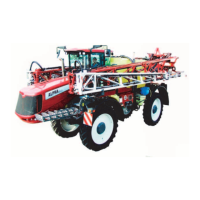
1. Assure that the speed ring is correctly fitted to the wheel, so that
the arrow (A) follows the rotation of the wheel in the forward
driving direction.
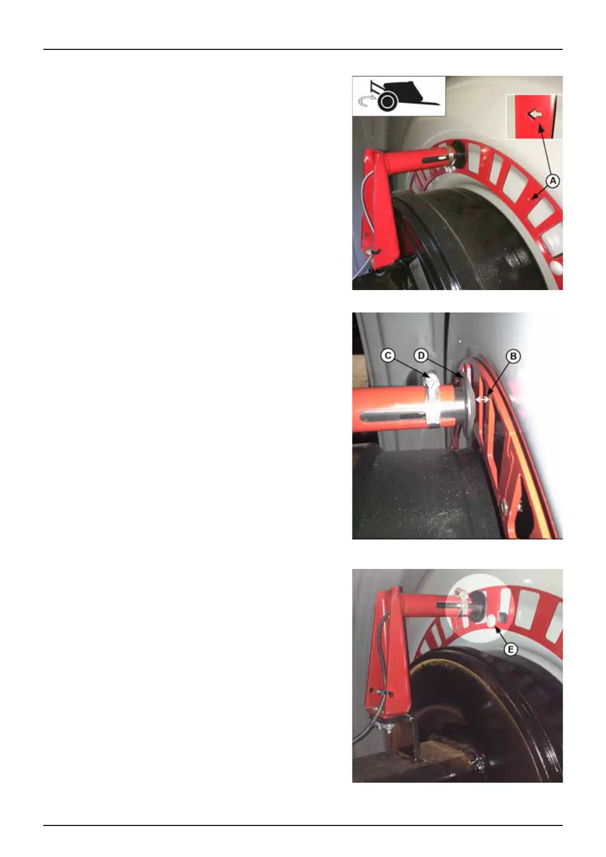
2. Check that the black sensor (D) lines up in the middle of the air
gaps in the speed ring when looking in vertical direction.
Distance from centre of the sensor to top of the brake drum:
• 412 mm brake drum = 60 mm
• 400 mm brake drum = 75 mm
3. Adjustment of the air gap begins with the sensor directly opposite
one of the bolts (E) holding the speed ring.
Loosen the clamp (C) to move the sensor (D) in or out of the red
tube. Retighten the clamp when finished.
Adjust the air gap (B) between sensor and speed ring to 4 mm.
Use a feeler gauge or similar tool.
4. After adjustment, spin up the wheel.
The air gap variation must be less than ± 0.5 mm for the sensor to
function correctly.
Check this at the entire circumference of the wheel.
5. Verify the speed on the controller.
μ
ATTENTION! Correct fitting is indicated by continuous flashing
from the transducer, when the wheel rotates.