- NOTE -
The spindle chiller hoses are connected to the machine at the factory.
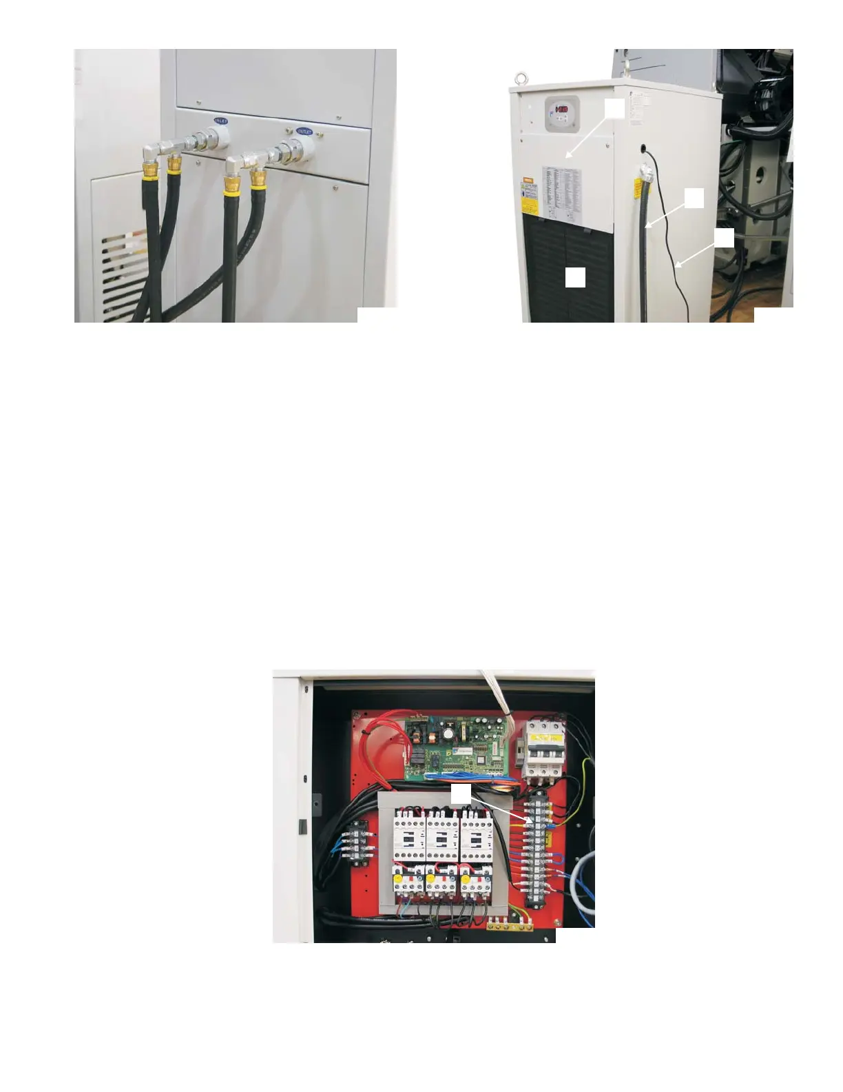
4. Route the chiller hoses to the chiller unit.
5. Remove the caps from the chiller unit INLET and OUTLET connections.
6. Connect the hoses to the chiller unit. Refer to Figure 1.34.
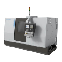
7. Remove air filter "F", Figure 1.35.
8. Remove access cover "C".
9. Connect conduit "D" to the chiller unit.
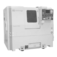
10. Remove the clear shield from terminal strip “G”, Figure 1.36.
M-507C 1-21
Figure 1.34 -Chiller Unit
Hose Connections
TP7873A
Figure 1.35 -Chiller Unit
Electrical Entrance
TP7874A
D
E
C
F
Figure 1.36 - Terminal Strip
Inside Chiller Unit
TP7877B
G