- NOTE -
Reference the wire markers on the bottom connections to the circuit breaker.
Connection information can also be referenced in the schematic suppled with the
machine.
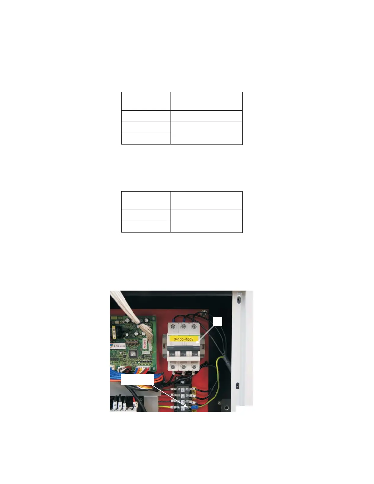
11. Connect the power wires in cable 308CBL to the top of circuit breaker "H", Figure 1.37, as
follows:
Wire
Number
Circuit Breaker
Connection
B1 R
B2 S
B3 T
12. Connect the ground wire (green/yellow) to terminal strip connection "E", as shown in Figure
1.37.
13. Connect the blue signal wires to the terminal strip as follows:
Wire
Number
Terminal Strip
Connection
5738 12
+24A 11
14. Insert temperature probe wire "E", Figure 1.35, into the chiller unit.
15. Connect the temperature probe wires to the terminal strip according to the wire labels.
1-22 M-507C
Figure 1.37 - Power Connection
at Circuit Breaker
TP8262
H
Ground Wire
Connection