M-507C 2-15
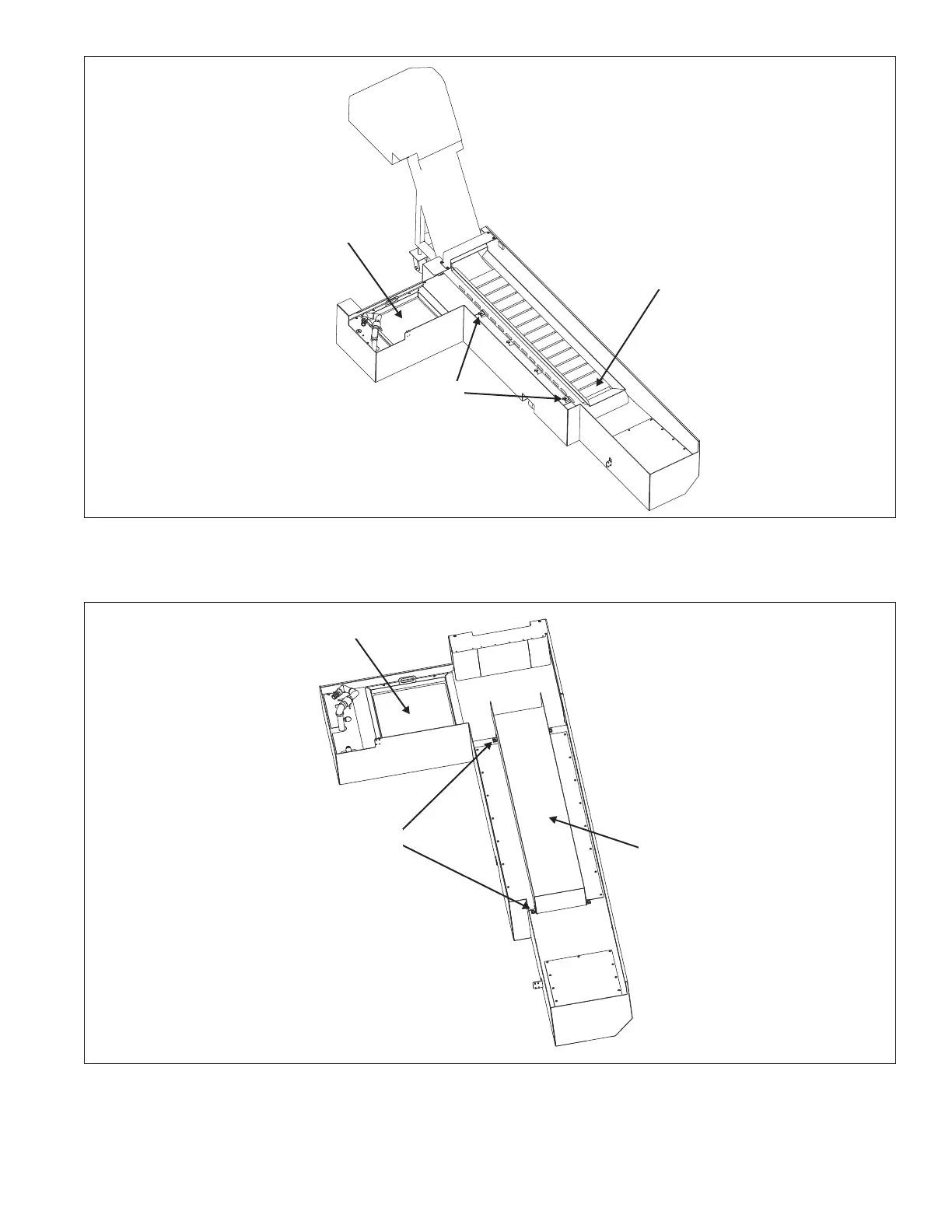
Figure 2.21 - Coolant Tank with Chip Conveyor
(T-42, T-51, and T-65 Lathes)
A
Support this end of the chip
conveyor during removal and
installation.
Chip Basket
TI5789
NOTE:
Two screws "A" located on each side of the chip conveyor.
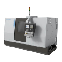
Figure 2.22 - Coolant Tank without Chip Conveyor
(T-51 and T-65 Lathes)
Chip Basket
B
C
TI5864
NOTE:
Two screws "B" located on each side of the tank liner.