HI 6600 Series Modular Sensor System User Guide
Page | 68
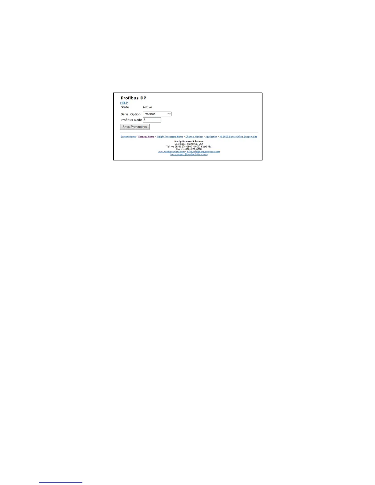
Configuring PROFIBUS from the Web Interface
1) From the web connection, choose Gateway > Configuration > Communications > Profibus.
then Click on
Profibus Card. to open then Click on Profibus Card form. Double
click in the Node text field to highlight the
current entry. Type in the HI 6600 Node address. Range:1-125 (default 5). The example below uses the default
address #5.
NOTE
Profibus Node Address #5 is the lowest number that can be used by a slave device.
2) Profibus on the HI 6600 Gateway does not have the Termination setting. The board has a switch on
it for turning on/off the termination. The switch is located next to the Profibus connector. The
switch and connector is also used for the Modbus RTU and the switch position is: Center = off,
termination for Profibus is to the right labeled T2 (to the left is termination for Modbus RTU labeled
T1).
3) Click Save Parameters to save the entry.
4) You can also read the communication state of the instrument (Active or Passive)
5) Click Home to return to the Home Page.
Initialization Process
To be able to add an HI 6600 to a Profibus-DP network, you need a PC or a PLC and software such as
Siemens Step 7™, Simatic Manager or the equivalent. The software must allow the Profibus-DP PLC and
the HI 6600 to exchange data.