VPL400-X: Install Manual
21JULY2023 | 630-00159 B
12
INSTALLATION
VPL400-X: SECTION 4
SECTION 4
INSTALLATION
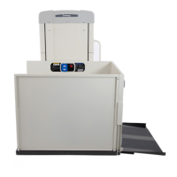
TOWER PREPARATION
1. Remove 5X front screws.
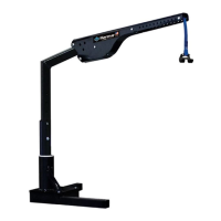
2. Remove the top cap by loosening the four (4)
side screws. See Figures 4-1.
Figure 4-1
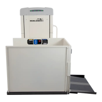
3. Remove the front panel by rotating it out
slightly and lifting it out of the lower slots.
See Figure 4-2.
Figure 4-2
4. Position the VPL tower close to the upper
landing and stand it up using appropriate
material handling processes.
NOTE: Tower frame should only be lifted by the
rectangular tubes below the top plate.
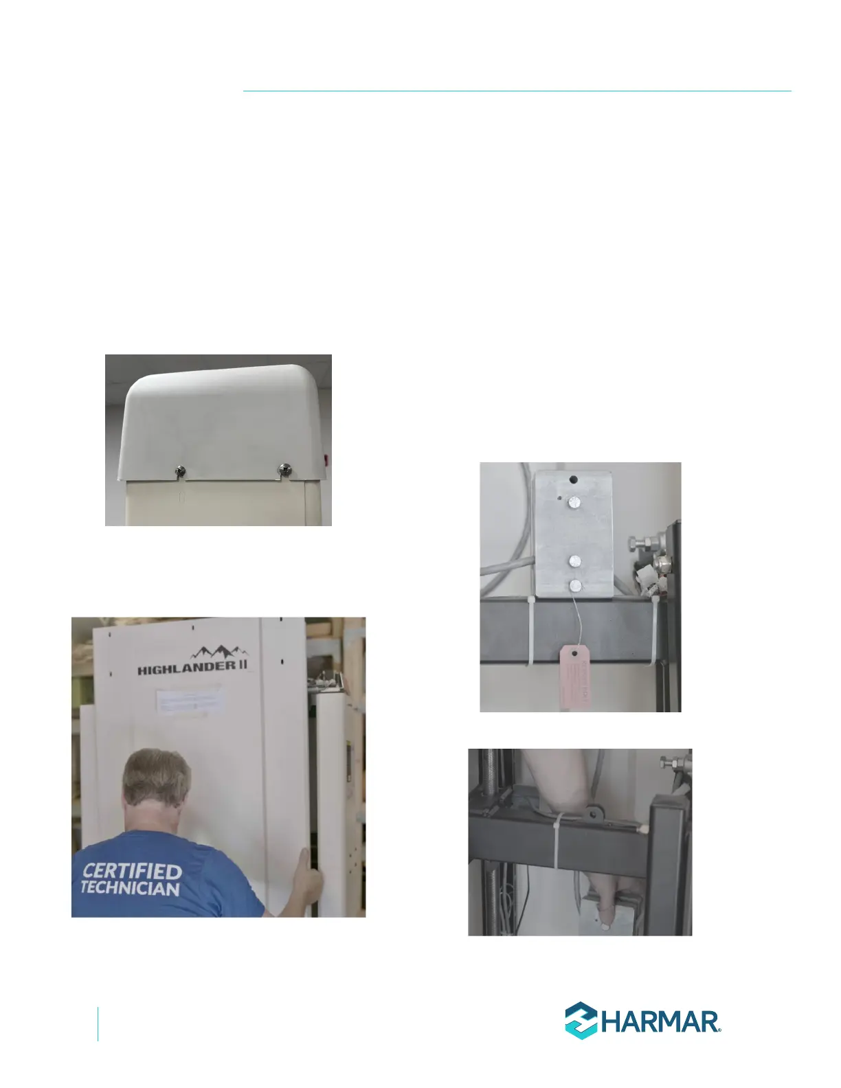
5. Remove and discard the temporary bolt and
pulley to the carriage for shipping. This bolt is
indicated with a red tag. Suspend the pulley
assembly behind the carriage.
See Figures 4-3 and 4-4.
Figure 4-3
Figure 4-4