VPL400-X: Install Manual
21JULY2023 | 630-00159 B
19
INSTALLATION
VPL400-X: SECTION 4
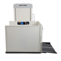
FASCIA PANEL
INSTALLATION
panel heights can be special ordered. Fascia panels
must provide a smooth surface for the platform
edge to run against to prevent any shear or
obstruction hazards. They must be fastened beneath
the opening and adjacent to each other with no
overlapping or gaps between them.
The upper landing of a deck with an opening
underneath requires a fascia wall.
NOTE: It may be necessary to stud up the wall to give the
fascia panel something to fasten to.
Once the structure is in place, fasten the fascia
panel to it.
"".
See Figure 4-28.
Figure 4-28
INSTALLING THE TOP
LANDING GATE
NOTE: If the call/send switch is installed in the gate, the
wires are routed between the gate and to the top of the
tower. If the call send is located outside the gate, the
wires are routed from the gate to the call send box and
then from the box to the top of the tower.
The top of the gate must be aached to a
supporng structure. The gate is not designed to
be freestanding. Reference Typical Drawing ENG-
000847 Landing Gates.
WARNING
!
1.
Disconnect all power before making any electrical
connecons.
WARNING
!
Remove small screws and post cover on both
sides of the landing gate with a No. 1 Phillips
screwdriver.
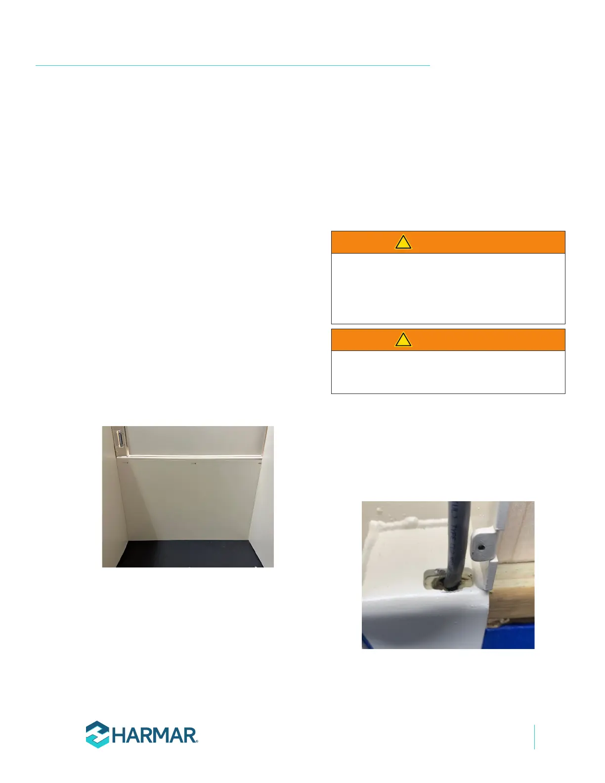
2. Create the necessary space below the gate sill
so the wire can be routed into the gate post
through the wire routing slot in the bottom of
the gate mounting flange. See Figure 4-29.
Figure 4-29