VPL400-X: Install Manual
21JULY2023 | 630-00159 B
15
INSTALLATION
VPL400-X: SECTION 4
ROUTING INTERLOCK &
CALL/SEND WIRES INSIDE
THE TOWER
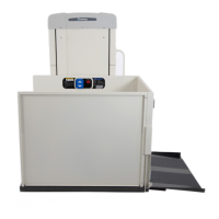
Depending on the configuration call/send and or
interlock wires will be wired directly to the control
board and coiled up at the top of the tower or will
be in the small parts box.
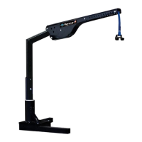
1. Uncoil any wires temporarily zip tied to the
underside of the tower top plate and route it
into the wire channel. See Figure 4-13.
Figure 4-13
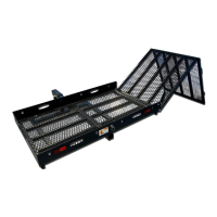
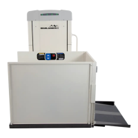
2. If the configuration comes with a coil of wire
in the small parts box, it must be connected to
the AC Controller/Travel Cable and routed to
the wire channel. See Figure 4-14.
Figure 4-14
Call/Send and interlock wires can be routed from the
top of the tower, into the wire channel, and out one
of the provided knockouts at the top or the bottom of
the tower side panels.
NOTICE
INSTALLING PLATFORM
GUARD PANELS STRAIGHT
THROUGH CONFIGURATION
1.
the small parts bag.
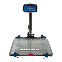
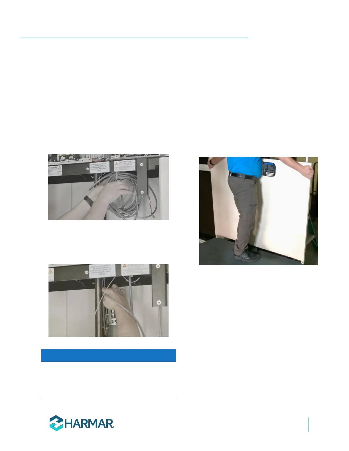
2. Insert the control side guard panel posts into
the pockets on the platform with the smooth
side facing the inside of the platform and
insert the outer panel into the outer pockets.
See Figure 4-15.
Figure 4-15
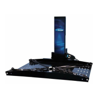
3.
" socket, torque bolts
down sufficiently to hold guard panels rigidly
in-place. The platform material in front of the
pockets may deform slightly while tightening
bolts. See Figure 4-16.