VPL400-X: Install Manual
21JULY2023 | 630-00159 B
13
INSTALLATION
VPL400-X: SECTION 4
NOTE: Be sure that the pulley assembly is suspended with
the sheeve at the top and that it is clear to move through
the lift range.
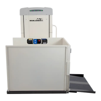
6. Connect the 8-pin platform control box, plug
to the matching 8-pin plug of the travel near
the top of the carriage flange. See Figure 4-5.
Figure 4-5
TEMPORARY ELECTRICAL
CONNECTION
1.
inside the tower. Retrieve the temporary power
cord from the parts kit. Route stripped end of
See Figure 4-6.
Figure 4-6
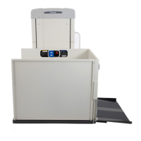
2. Connect the black wire to the back wire, white
wire to the white wire, and connect the green
wire to the green wire. See Figure 4-7.
Figure 4-7
3.
Verify that hot, neutral and ground conductors
where the temporary power cord will connect are
correct. Incorrect wiring or lack of ground could
cause unit malfuncon.
WARNING
!
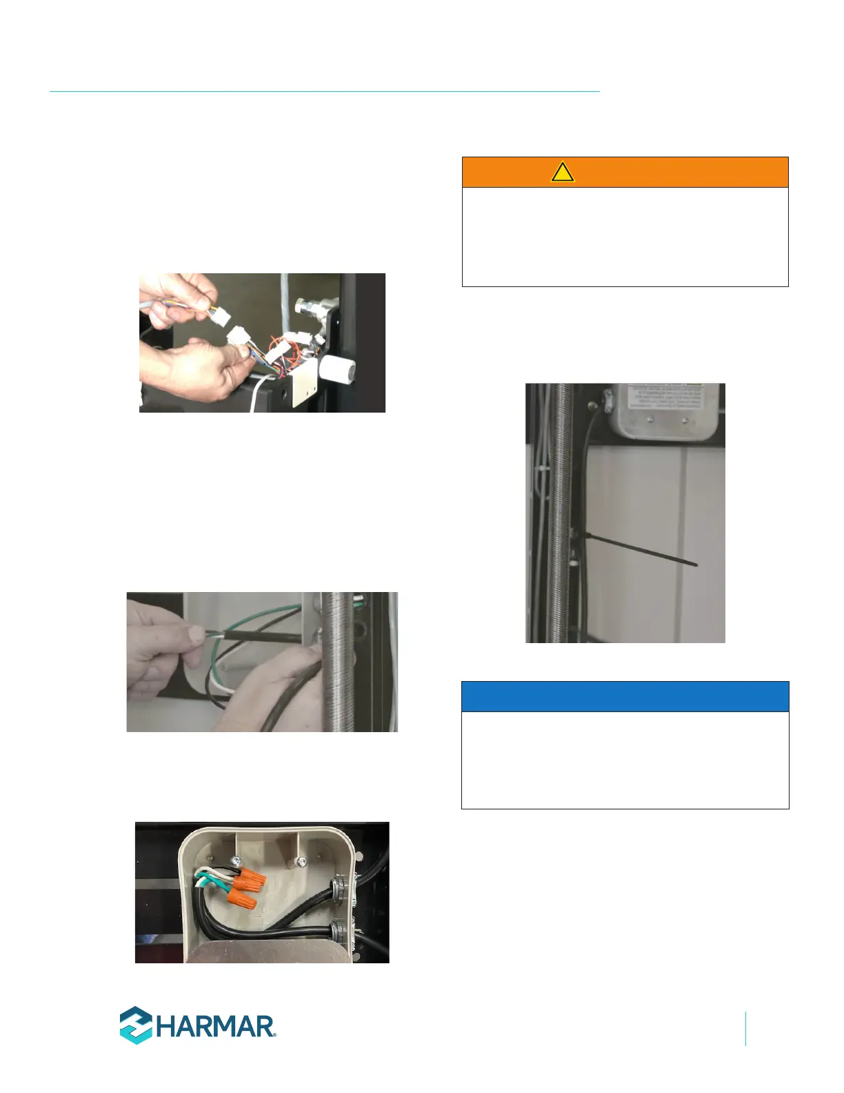
Route the temporary cord along the wire
channel, run it through one of the knockout
holes at the top or bottom of the large side
panels and then plug it into 120-volt source
outlet. See Figure 4-8.
Figure 4-8
This section is for supplying temporary power to the
lift for positioning and installation. If permanent
power is being implemented at this stage, please refer
to page 24 for permanent power installation.
NOTICE