VPL400-X: Install Manual
21JULY2023 | 630-00159 B
24
INSTALLATION
VPL400-X: SECTION 4
PERMANENT POWER
INSTALLATION
Permanent power can be installed at various points
VPL must be wired to a dedicated circuit, connected
through a 2-pole fused and lockable disconnect,
providing a 120V AC power supply (15-amp breaker).
See Figure 4-40 and reference enclosed for wiring details.
Figure 4-40
OUTSIDE TOWER
CONDUIT
DPST FUSED DISCONNECT
G
G
N
L
S/L
INSIDE TOWER
JUNCTION BOX
5X WIRE NUTS
Route wiring from disconnect to tower as directly
as possible and enter the tower through most
convenient knock-out in the tower side panels. Inside
the tower enclosure, route wires from knockout to
enclosure. Use the backside of the wire channel if the
sure all wiring is routed clear of the moving carriage
and roller wheels inside the tower. See Figure 4-41.
Figure 4-41
Knockout
Wire Channel
Junction Box
FINAL INSTALLATION
Jumpers MUST be removed at compleon of
installaon and conrm safety features are
operaonal.
WARNING
!
When the platform is mounted and the upper/lower
landings are ready to be wired in:
1. Wire in the upper landing interlock and call/
send.
2.
gate cable shown. See Figure 6-2 on page 29.
3. Remove the safety pan jumper and plug in the
platform safety pan harness.
4. Mount the cab control on the platform guard
panel.
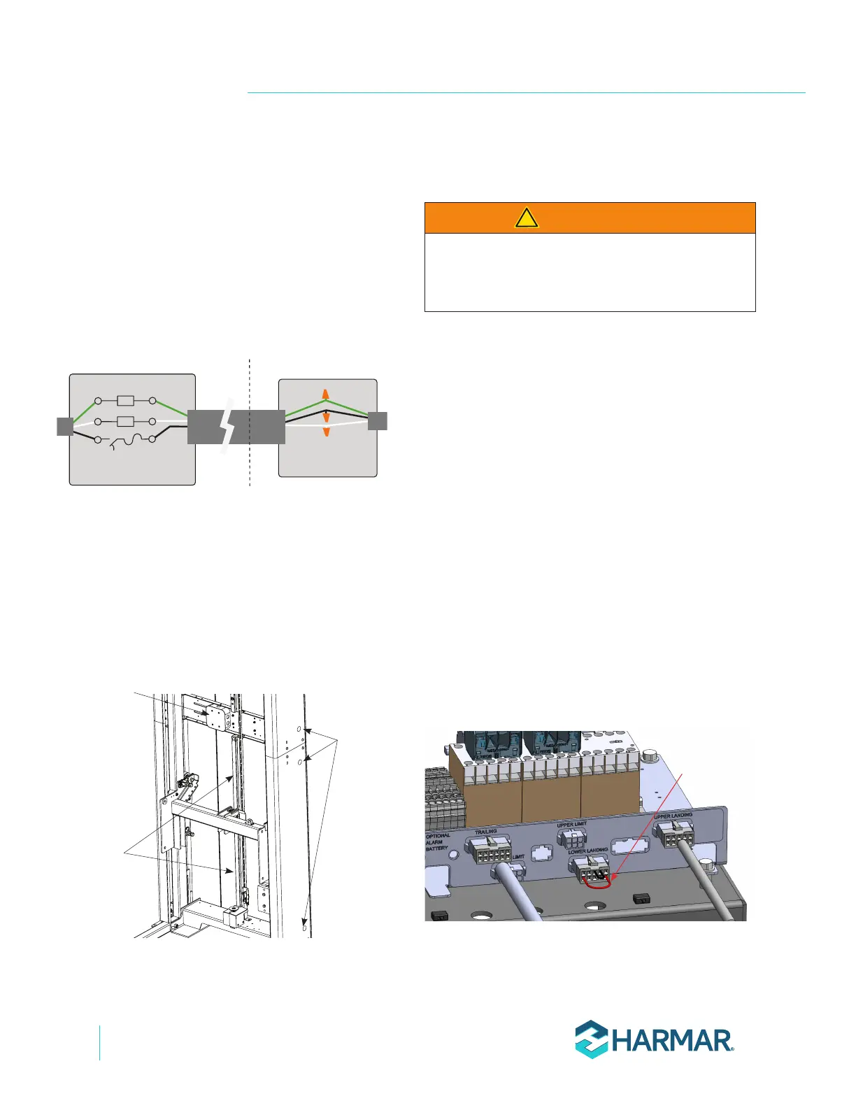
5. If there is a lower landing call/send, replace
the lower landing jumper connector with the
lower landing cable and route the cable to the
lower landing call/send and connect the wires
as shown. See Figure 6-3 on page 31.
IF THERE IS NO LOWER LANDING CALL/
SEND, CUT THE RED JUMPER WIRE.
See Figure 4-42.
Figure 4-42
Lower Landing
Red Jumper
Wire